Packed Geometry Maps

Geometry Map.png

Here, I present a novel implementation of well established techniques I am calling “Packed Geometry Maps”. By swizzling color channels and exploiting current compression techniques, packed geometry maps represent normal, height, and occlusion information in a single texture asset. This texture is fully backwards-compatible with standard normal maps in the Unity game engine, and can be automatically generated from traditional input texture maps through an extension of the Unity editor, reducing texture memory requirements by 2/3, and requiring no changes to developer workflow.

Normal Maps are great, but they could be better.

Normal maps are not a new invention. The initial concept was first published sometime around 1998 as a technique for storing high-frequency surface data to be re-mapped onto low resolution geometry. Since then, normal maps in some for or another have become ubiquitous in realtime computer graphics, where the geometric resolution of models may be limited.

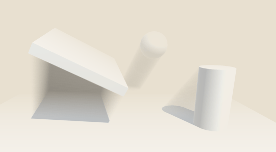
The basic concept is to store surface normals (the direction a surface is “facing”), in an image. When you need to know this information, such as when calculating shading on an object, you simply look up the surface normal from the texture (and depending on your implementation, re-project it into a different basis). The end result is low resolution models being shaded as though they were higher detail, capturing smaller bumps and cracks in their surface which aren’t actually represented by geometry.

Normal Map Example.png

A comparison of a simple sphere without and with normal mapping. The underlying geometry is the same for both.

Normal maps are fantastic, but as computer hardware advances other techniques have become more frequent in addition to normal mapping. Runtime tessellation for example, produces additional geometric detail to better represent rough surfaces, and produce more accurate silhouettes, at the expense of additional texture data. Ambient occlusion maps are used to represent light absorption and scattering in complex geometry, and all of these new effects require new texture data as input. The normal map should not be discounted or ignored, but there’s definitely room for improvement here!

What’s In A Normal Map?

Surface normals are typically represented by colors, using the normal RGB format. The red channel of color is used to represent the “x” component of the normal vector (usually the coordinate along the surface tangent), green for “y” (bitangent), and blue for “z” (normal). These components all sum up to create a unit-length vector, used in lighting calculations, etc. which is stored in the final normal map texture.

You might have already noticed an optimization here. If the normal vector is known to be unit-length, then why are we storing three components? In most situations, the Z component of the surface normal in tangent-space is positive, and close to one. Using these assumptions, we can remove any ambiguity in solving for the Z component, and it can be reconstructed using only the X and Y components, which contain more critical signed data.

This allows us to completely remove one color channel from our normal map texture, while still preserving all the information required to properly shade an object!

In fact, the Unity game engine already does this! Unity uses a texture compression format called DXT5nm, a specific use-case of standard DXT5 compression. This confers many advantages in terms of memory usage by sacrificing precision and image quality. The DXT5 compression format is unique in that it preserves a fixed compression ratio, and the overall quality of the output image is dependent on the content of the image itself. I won’t get into details here, but images containing shades of a single color have a higher compressed quality than images with multiple colors. Unity disposes of the “Z” component of normal maps, and swizzles the X component into the alpha channel to take advantage of the inherent strengths of the format, and reduce the number of visible artifacts after compression.

What About Those Two Extra Channels?

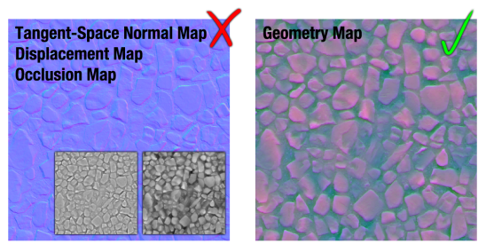
So, the Unity game engine simply writes zeroes into two of the color channels used by normal maps. Granted, this increases the quality of the texture due to the subtleties of DXT5 compression, but we could easily store two more low-frequency channels without a significant loss in quality. For this, I’ve opted to store ambient occlusion in red, and displacement in blue. By placing ambient occlusion (which tends to have the lowest contrast of all the input maps) in red, we can generally reduce the number of artifacts visible in the green channel of the surface normals, where they are most noticeable. Imprecision and compression artifacts in displacement and occlusion maps are also much less visible, due to the low-frequency nature of the types of data typically stored here.

Geometry Vs Traditional.png

The traditional normal, ambient occlusion, and displacement maps (left), compared to packed geometry maps (right). While geometry maps exhibit some artifacts, they’re not particularly noticeable on matte surfaces.

mirror-artifacts

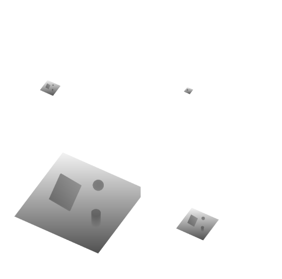
Worst-case example of Packed Geometry Maps applied to a mirror sphere.

This technique tends to work quite well. The majority of the texture artifacts produced are relatively subtle on mostly matte surfaces, however it still looks considerably worse on highly metallic and reflective surfaces, and therefore is mostly recommended for environment textures. On mostly non-metal surfaces such as dirt, grass, or wood, the differences between a packed geometry map and a traditional multi-texture setup are largely imperceptible, and given the constant compression ratio of DXT5, will require 1/3 the texture memory of the equivalent traditional input maps.

Won’t This Change Our Workflow?

As a matter of fact, no. Since packed geometry maps are essentially a combination of the color channels of various input textures, they can be produced automatically as part of the import pipeline of your game engine.

I’ve written a seamless extension to the Unity engine which will automatically build geometry maps for input textures as they are imported, updating them as source assets change, and saving them as unique standalone assets that can be incorporated in the final build.

By adding this extension to your project, geometry maps will be generated automatically as you import and update source texture maps. The utility is configurable and allows manual generation, as well as adding asset labels to generated geometry maps for easy searches. Certain directories can also be excluded if they contain textures your team does not want generating maps, and the file suffixes used to identify different texture types can be configured to best suit your naming scheme. It supports live reloading when source assets are changed, and is designed to be unobtrusive as possible.

There are a few minor issues left with the editor extension, so I’m not ready to release it just yet, but I’ll post it to Github in the near future!

Using these new Geometry Maps are just as simple! I’ve written a CG-Include file which defines a simple function for unpacking geometry maps, which should serve as a mostly drop-in replacement for Unity’s “UnpackNormal” function. Unlike “UnpackNormal” however, the “UnpackGeometryMap” function only requires a single texture sample for all three input maps, and returns a struct type for convenient access.

#include “GeometryMap.cginc”

// defines three values
//     geo.normal
//     geo.displacement
//     geo.occlusion
GeometryMapSample geo = UnpackGeometryMap(tex2D(_GeoMap, IN.uv));

Including Geometry Map support in your new shaders is a snap and, should you choose, geometry maps are fully backwards-compatible with Unity’s built-in normal maps, and can simply be dropped in the “Normal Map” field of any standard shader.

In Summary

By utilizing unused texture color channels, it is possible to sacrifice some image quality for considerable savings on texture memory. A single texture map can be generated to produce backwards compatible geometry maps, representing normal, displacement, and occlusion information without considerable changes to artists’ workflow. This technique is particularly applicable to realtime applications designed to run on low-end hardware where texture memory is of significant concern, and is suitable for representing most non-metal surfaces.

In the future, I’ll look into other compression techniques that don’t degrade with additional color channels. Even if the compressed size of a single map is larger, there could still be potential for savings when compared to several DXT5 textures.

Screenspace Volumetric Shadowing

Let’s get this out of the way first, you can download a demo of the effect for Windows and Mac here!

So recently I decided to learn a little more about the Unity engine’s rendering pipeline. I had a pretty good high-level idea, but the actual stages of the process were a mystery to me. “…then it does lighting…” is not necessarily a useful level of granularity.  After a week with the documentation, and the fabulous Frame Debugger added in Unity 5, I’m fairly confident in my understanding of some of the nitty-gritty of shading.

“What do we gain from knowing this? I drop a few lights in my scene and it all works just fine!” – well, with a solid understanding of the rendering and shading pipeline, it becomes much easier to extend the process of “just dropping lights in a scene” for much greater effect. This week, I wrote a screen-space volumetric shadowing effect using CommandBuffers and a few fancy shader programs.

SSVS_Comparison.png

The effect is fairly subtle, but atmospheric scattering (the reflection of light off of tiny particles suspended in the air) is fairly important. It helps to contribute a sense of space to a scene, helps to clue the brain in on where light-sources are, and can be used to hint at the mood of a scene. Is it early morning in a dense fog, or a clear summer evening?

Now the more eagle-eyed among you will notice that I didn’t implement atmospheric scattering. This effect is actually an attempt at the opposite, estimating the thickness of shadows in the scene, and darkening areas to negate the scattering approximation of a uniform fog. Tradiational “Distance Fog” is meant to simulate light-scattering in a scene, blending objects in the distance into a uniform medium color. This effect is extremely cheap to compute, and fairly well established. I intended my shadowing system to be applied on top of existing art, and so a complete lighting overhaul was impossible as it would require designers and artists to step through a scene and update every light they’ve placed. It makes very little sense in a scene like the one above, where there isn’t any fog, but when thrown into a scene with fog and lighting, it can look quite nice.

SSVS.png

SSVS with traditional “distance fog”

My approximation clearly isn’t “correct” to real-world lighting. Shadows are the lack of light behind an occluder, not a painted-over darkness multiplied over the background, but as a first draft, it looks quite nice.

So let’s look at how this was done, and what I intend to do in the future.

Technical Explanation

Unity 5.3 introduced something called Graphics CommandBuffers. These are essentially a hook into the rendering pipeline in the form of queues of rendering instructions you can inject at various points. When my scene is loaded, I would initialize and attach a CommandBuffer to “CameraEvent.BeforeLighting” for example, and whatever commands are in that buffer would be executed every time the camera prepares to render lighting. When you’re finished, and don’t want your code to be called again, you remove it from the pipeline, and it stops being executed.

My shadowing effect attaches a minimum of four such buffers, listed here in order of execution during a frame.

  1. CameraEvent.BeforeLighting
  2. LightEvent.AfterShadowMap (for each scene light)
  3. LightEvent.AfterScreenspaceMask (for each scene light)
  4. CameraEvent.BeforeImageEffects

1) CameraEvent.BeforeLighting

CommandBuffers attached to this event are executed every frame before any lighting calculations take place.

The camera rendering the scene creates a new render target, called the “shadowBuffer” when it’s initialized, which will contain the added effects of all the lights in our scene. Every frame before any lighting takes place, this buffer is cleared to a white color. That’s the only thing done in the “beforeLighting” stage, but it’s critical to the effect working. If the buffer weren’t cleared, then the effects of the previous frame would be blended into the next, and you’d quickly get a muddy mess…

2) LightEvent.AfterShadowMap

ssvs_shadowmap

A cascaded shadowmap resulting from the shadowmap pass on a Directional Light. Color represents distance from the light source.

CommandBuffers attached to this event are executed every time a shadowmap is rendered for a particular light. Excuse my egregious use of bold, but this was one of the most critical parts of the effect, and seems to cause an extreme amount of confusion online (The working code has been reported as a bug in Unity at least 3 times now).

This means that whenever a shadowmap is rendered for a light for any reason (including the Scene View Camera in the Unity Editor!), your CommandBuffer will be called.

In this stage of the rendering pipeline, I bind the currently active render target to a global shader property. Immediately before this stage in the pipeline, the shadowmaps for the light were being rendered, so they should still be the active render target. By binding them to a shader property, I allow future stages in the pipeline to access them!

For most lights, this is all that happens and we could just render our effect here, but “directional lights” are a special case. They render screen-space masks which are sampled by the shading stage of the deferred or forward pipeline. This allows for more complex shadow filtering, and eliminates the texture lookup that might have been performed on occluded fragments. The proper transformations performed by the engine to convert world-space positions to light-space positions aren’t yet initialized for Directional Lights at this stage in the pipeline, which brings us to…

3) LightEvent.BeforeScreenspaceMask

ssvs_raymarch

The results of the raymarch shadow accumulation pass. Darker areas counted more shadowed samples.

Commands attached to this event will be executed every time a directional light is preparing to build a screenspace shadow mask as described above. It’s at this stage that Unity populates all of the transformation matrices to convert back and forth between world-space and light-space, which we coincidentally need. This is where the actual meat of the effect take place.

When this happens, the attached CommandBuffer instructs the light to render a pass into the camera’s shadowBuffer we allocated and cleared earlier. During this pass, a simple raymarch is performed in screen-space, essentially stepping through the world and checking whether or not a sample point in 3D space is in shadow or not. Here, the raymarch samples the shadowmap bound in step 2, and uses the transformation matrices bound in step 3, before counting up the number of sample points that were in shadow, and rendering that as a color (black for all shadows, white for none) into the camera’s shadowBuffer. This final color is actually multiplied with the color already in the buffer, so if two shadows overlap, they will both darken the pixels in the buffer, rather than over-writing eachother. (A more technically correct solution would be to take the minimum value of the two samples, rather than multiplying them, but then I couldn’t take advantage of hardware blend-modes, and would need a separate pass).

4) CameraEvent.BeforeImageEffects

Now for the last stage in the effect. Raymarching is quite expensive, so most of the time, the previous pass is performed at a lower resolution of 1/2, 1/4, or even 1/8. Before the user sees it, we need to blow it back up to fullscreen! Notice that there’s also quite a bit of noise in the raw raymarch data. This is because I used a dithered sampling scheme to better capture high-resolution data. We don’t want any of that in the final composite, so first, we perform a two step Gaussian blur on the low resolution raymarch data. This will effectively soften the image, and smooth out noise. Normally this isn’t a great idea because it removes high-frequency data, but because shadows are relatively “soft” anyway, it works quite well in this case. The blur also takes into account the depth of the scene, and won’t blur together two pixels if their depths are extremely different. This is useful for preserving hard edges where two surfaces meet, or between a background object and a foreground object.

Lastly, we perform a bilateral upsample back to full resolution. This is pretty much a textbook technique now, but it’s still quite effective!

5?) Considerations

There are a few considerations that are very important here. First, CommandBuffers aren’t executed inline with the rest of your scripts, they’re executed separately in the rendering pipeline. Second, when you bind a commandBuffer to an event, it will be executed every time that event occurs. This can cause issues with the Scene View Camera in the editor. It is only used for setting up your scene, but it actually triggers Light Events too!

I worked around this by adding an “OnPreRender” callback to my cameras, which re-build the commands in the Light command buffers before every frame, and then another in “OnPostRender” which tears them all down. This is absolutely critical because otherwise, the scene camera, and other cameras you may not want rendering your effects will trigger them, wasting precious resources and sometimes putting data where you don’t think it will go (For example, the scene camera triggered the same CommandBuffer as the game camera, causing the scene’s shadows to be rendered into the shadowBuffer, which caused all sorts of problems!)

As long as you think critically about what you’re actually instructing the engine to do, this shouldn’t be too bad, but I lost too many hours to this sort of issue :\

Wrapping Up

And that’s about it! I hope this gave at least some high-level insight into how you could use CommandBuffers for new effects!

In the future, I’d like to extend this to a complete volumetric lighting system, rather than just a simple shadowing demo, but for now I’m quite happy with the result!

If you want to check it out for yourself, you can download a demo here!