Interior Mapping – Part 2

In part 1, we discussed the requirements and rationale behind Interior Mapping. In this second part, we’ll discuss the technical implementation of what I’m calling (for lack of a better title) “Tangent-Space Interior Mapping”.

Coordinates and Spaces

In the original implementation, room volumes were defined in object-space or world-space. This is by far the easiest coordinate system to work in, but it quickly presents a problem! What about buildings with angled or curved walls? At the moment, the rooms are bounded by building geometry, which can lead to extremely small rooms in odd corners and uneven or truncated walls!

In reality, outer rooms are almost always aligned with the exterior of the building. Hallways rarely run diagonally and are seldom narrower at one end than the other! We would rather have all our rooms aligned with the mesh surface, and then extruded inward towards the “core” of the building.

Cylindrical Building

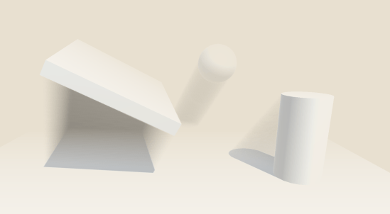
Curved rooms, just by changing the coordinate basis.

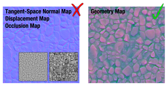
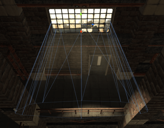
In order to do this, we can just look for an alternative coordinate system for our calculations which lines up with our surface (linear algebra is cool like that). Welcome to Tangent Space! Tangent space is already used elsewhere in shaders. Even wonder why normal-maps are that weird blue color? They actually represent a series of directions in tangent-space, relative to the orientation of the surface itself. Rather than “Forward”, a Z+ component normal map points “Outward”. We can simply perform the raycast in a different coordinate basis, and suddenly the entire problem becomes surface-relative in world-space, while still being axis-aligned in tangent space! A neat side-effect of this is that our room volumes now follow the curvature of the building, meaning that curved facades will render curved hallways running their length, and always have a full wall parallel to the building exterior.

While we’re at it, what if we used a non-normalized ray? Most of the time, a ray should have a normalized direction. “Forward” should have the same magnitude as “Right”. If we pre-scale our ray direction to match room dimensions, then we can simplify it out of the problem. So now, we’re performing a single raycast against a unit-sized axis-aligned cube!

Room Textures

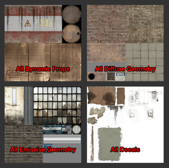
The original publication called for separate textures for walls, floors, and ceilings. This works wonderfully, but I find it difficult to work with. Keeping these three textures in sync can get difficult, and atlasing multiple room textures together quickly becomes a pain. Alternative methods such as the one proposed by Zoe J Wood in “Interior Mapping Meets Escher” utilizes cubemaps, however this makes atlasing downright impossible, and introduces new constraints on the artists building interior assets.
interior_atlas
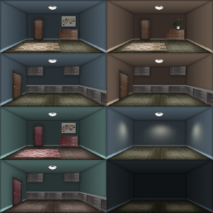
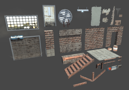
Andrew Willmott briefly touched on an alternative in “From AAA to Indie: Graphics R&D”, which used a pre-projected interior texture for the interior maps in SimCity. This was the format I decided to use for my implementation, as it is highly author-able, easy to work with, and provides results only slightly worse than full cubemaps. A massive atlas of room interiors can be constructed on a per-building basis, and then randomly selected. Buildings can therefore easily maintain a cohesive interior style with random variation using only a single texture resource.

Finally, The Code

I’ve excluded some of the standard Unity engine scaffolding, so as to not distract from the relevant code. You won’t be able to copy-paste this, but it should be easier to see what’s happening as a result.

v2f vert (appdata v) {
   v2f o;
   
   // First, let's determine a tangent basis matrix.
   // We will want to perform the interior raycast in tangent-space,
   // so it correctly follows building curvature, and we won't have to
   // worry about aligning rooms with edges.
   half tanSign = v.tangent.w * unity_WorldTransformParams.w;
   half3x3 objectToTangent = half3x3(
      v.tangent.xyz,
      cross(v.normal, v.tangent) * tanSign,
      v.normal);

   // Next, determine the tangent-space eye vector. This will be
   // cast into an implied room volume to calculate a hit position.
   float3 oEyeVec = v.vertex - WorldToObject(_WorldSpaceCameraPos);
   o.tEyeVec = mul(objectToTangent, oEyeVec);

   // The vertex position in tangent-space is just the unscaled
   // texture coordinate.
   o.tPos = v.uv;

   // Lastly, output the normal vertex data.
   o.vertex = UnityObjectToClipPos(v.vertex);
   o.uv = TRANSFORM_TEX(v.uv, _ExteriorTex);

   return o;
}

fixed4 frag (v2f i) : SV_Target {
   // First, construct a ray from the camera, onto our UV plane.
   // Notice the ray is being pre-scaled by the room dimensions.
   // By distorting the ray in this way, the volume can be treated
   // as a unit cube in the intersection code.
   float3 rOri = frac(float3(i.tPos,0) / _RoomSize);
   float3 rDir = normalize(i.tEyeVec) / _RoomSize;

   // Now, define the volume of our room. With the pre-scale, this
   // is just a unit-sized box.
   float3 bMin = floor(float3(i.tPos,-1));
   float3 bMax = bMin + 1;
   float3 bMid = bMin + 0.5;

   // Since the bounding box is axis-aligned, we can just find
   // the ray-plane intersections for each plane. we only 
   // actually need to solve for the 3 "back" planes, since the 
   // near walls of the virtual cube are "open".
   // just find the corner opposite the camera using the sign of
   // the ray's direction.
   float3 planes = lerp(bMin, bMax, step(0, rDir));
   float3 tPlane = (planes - rOri) / rDir;

   // Now, we know the distance to the intersection is simply
   // equal to the closest ray-plane intersection point.
   float tDist = min(min(tPlane.x, tPlane.y), tPlane.z);

   // Lastly, given the point of intersection, we can calculate
   // a sample vector just like a cubemap.
   float3 roomVec = (rOri + rDir * tDist) - bMid;
   float2 interiorUV = roomVec.xy * lerp(INTERIOR_BACK_PLANE_SCALE, 1, roomVec.z + 0.5) + 0.5;

#if defined(INTERIOR_USE_ATLAS)
   // If the room texture is an atlas of multiple variants, transform
   // the texture coordinates using a random index based on the room index.
   float2 roomIdx = floor(i.tPos / _RoomSize);
   float2 texPos = floor(rand(roomIdx) * _InteriorTexCount) / _InteriorTexCount;

   interiorUV /= _InteriorTexCount;
   interiorUV += texPos;
#endif

   // lastly, sample the interior texture, and blend it with an exterior!
   fixed4 interior = tex2D(_InteriorTex, interiorUV);
   fixed4 exterior = tex2D(_ExteriorTex, i.uv);

   return lerp(interior, exterior, exterior.a);
}

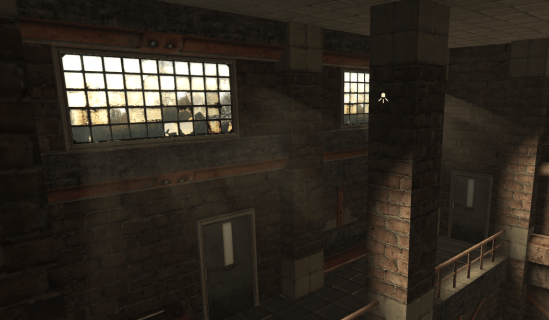
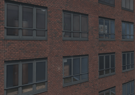
And that’s pretty much all there is to it! The code itself is actually quite simple and, while there are small visual artifacts, it provides a fairly convincing representation of interior rooms!


Interior + Exterior Blend
https://gfycat.com/FrankSoftAvocet


There’s definitely more room for improvement in the future. The original paper supported animated “cards” to represent people and furniture, and a more realistic illumination model may be desirable. Still, for an initial implementation, I think things came out quite well!

Packed Geometry Maps

Geometry Map.png

Here, I present a novel implementation of well established techniques I am calling “Packed Geometry Maps”. By swizzling color channels and exploiting current compression techniques, packed geometry maps represent normal, height, and occlusion information in a single texture asset. This texture is fully backwards-compatible with standard normal maps in the Unity game engine, and can be automatically generated from traditional input texture maps through an extension of the Unity editor, reducing texture memory requirements by 2/3, and requiring no changes to developer workflow.

Normal Maps are great, but they could be better.

Normal maps are not a new invention. The initial concept was first published sometime around 1998 as a technique for storing high-frequency surface data to be re-mapped onto low resolution geometry. Since then, normal maps in some for or another have become ubiquitous in realtime computer graphics, where the geometric resolution of models may be limited.

The basic concept is to store surface normals (the direction a surface is “facing”), in an image. When you need to know this information, such as when calculating shading on an object, you simply look up the surface normal from the texture (and depending on your implementation, re-project it into a different basis). The end result is low resolution models being shaded as though they were higher detail, capturing smaller bumps and cracks in their surface which aren’t actually represented by geometry.

Normal Map Example.png

A comparison of a simple sphere without and with normal mapping. The underlying geometry is the same for both.

Normal maps are fantastic, but as computer hardware advances other techniques have become more frequent in addition to normal mapping. Runtime tessellation for example, produces additional geometric detail to better represent rough surfaces, and produce more accurate silhouettes, at the expense of additional texture data. Ambient occlusion maps are used to represent light absorption and scattering in complex geometry, and all of these new effects require new texture data as input. The normal map should not be discounted or ignored, but there’s definitely room for improvement here!

What’s In A Normal Map?

Surface normals are typically represented by colors, using the normal RGB format. The red channel of color is used to represent the “x” component of the normal vector (usually the coordinate along the surface tangent), green for “y” (bitangent), and blue for “z” (normal). These components all sum up to create a unit-length vector, used in lighting calculations, etc. which is stored in the final normal map texture.

You might have already noticed an optimization here. If the normal vector is known to be unit-length, then why are we storing three components? In most situations, the Z component of the surface normal in tangent-space is positive, and close to one. Using these assumptions, we can remove any ambiguity in solving for the Z component, and it can be reconstructed using only the X and Y components, which contain more critical signed data.

This allows us to completely remove one color channel from our normal map texture, while still preserving all the information required to properly shade an object!

In fact, the Unity game engine already does this! Unity uses a texture compression format called DXT5nm, a specific use-case of standard DXT5 compression. This confers many advantages in terms of memory usage by sacrificing precision and image quality. The DXT5 compression format is unique in that it preserves a fixed compression ratio, and the overall quality of the output image is dependent on the content of the image itself. I won’t get into details here, but images containing shades of a single color have a higher compressed quality than images with multiple colors. Unity disposes of the “Z” component of normal maps, and swizzles the X component into the alpha channel to take advantage of the inherent strengths of the format, and reduce the number of visible artifacts after compression.

What About Those Two Extra Channels?

So, the Unity game engine simply writes zeroes into two of the color channels used by normal maps. Granted, this increases the quality of the texture due to the subtleties of DXT5 compression, but we could easily store two more low-frequency channels without a significant loss in quality. For this, I’ve opted to store ambient occlusion in red, and displacement in blue. By placing ambient occlusion (which tends to have the lowest contrast of all the input maps) in red, we can generally reduce the number of artifacts visible in the green channel of the surface normals, where they are most noticeable. Imprecision and compression artifacts in displacement and occlusion maps are also much less visible, due to the low-frequency nature of the types of data typically stored here.

Geometry Vs Traditional.png

The traditional normal, ambient occlusion, and displacement maps (left), compared to packed geometry maps (right). While geometry maps exhibit some artifacts, they’re not particularly noticeable on matte surfaces.

mirror-artifacts

Worst-case example of Packed Geometry Maps applied to a mirror sphere.

This technique tends to work quite well. The majority of the texture artifacts produced are relatively subtle on mostly matte surfaces, however it still looks considerably worse on highly metallic and reflective surfaces, and therefore is mostly recommended for environment textures. On mostly non-metal surfaces such as dirt, grass, or wood, the differences between a packed geometry map and a traditional multi-texture setup are largely imperceptible, and given the constant compression ratio of DXT5, will require 1/3 the texture memory of the equivalent traditional input maps.

Won’t This Change Our Workflow?

As a matter of fact, no. Since packed geometry maps are essentially a combination of the color channels of various input textures, they can be produced automatically as part of the import pipeline of your game engine.

I’ve written a seamless extension to the Unity engine which will automatically build geometry maps for input textures as they are imported, updating them as source assets change, and saving them as unique standalone assets that can be incorporated in the final build.

By adding this extension to your project, geometry maps will be generated automatically as you import and update source texture maps. The utility is configurable and allows manual generation, as well as adding asset labels to generated geometry maps for easy searches. Certain directories can also be excluded if they contain textures your team does not want generating maps, and the file suffixes used to identify different texture types can be configured to best suit your naming scheme. It supports live reloading when source assets are changed, and is designed to be unobtrusive as possible.

There are a few minor issues left with the editor extension, so I’m not ready to release it just yet, but I’ll post it to Github in the near future!

Using these new Geometry Maps are just as simple! I’ve written a CG-Include file which defines a simple function for unpacking geometry maps, which should serve as a mostly drop-in replacement for Unity’s “UnpackNormal” function. Unlike “UnpackNormal” however, the “UnpackGeometryMap” function only requires a single texture sample for all three input maps, and returns a struct type for convenient access.

#include “GeometryMap.cginc”

// defines three values
//     geo.normal
//     geo.displacement
//     geo.occlusion
GeometryMapSample geo = UnpackGeometryMap(tex2D(_GeoMap, IN.uv));

Including Geometry Map support in your new shaders is a snap and, should you choose, geometry maps are fully backwards-compatible with Unity’s built-in normal maps, and can simply be dropped in the “Normal Map” field of any standard shader.

In Summary

By utilizing unused texture color channels, it is possible to sacrifice some image quality for considerable savings on texture memory. A single texture map can be generated to produce backwards compatible geometry maps, representing normal, displacement, and occlusion information without considerable changes to artists’ workflow. This technique is particularly applicable to realtime applications designed to run on low-end hardware where texture memory is of significant concern, and is suitable for representing most non-metal surfaces.

In the future, I’ll look into other compression techniques that don’t degrade with additional color channels. Even if the compressed size of a single map is larger, there could still be potential for savings when compared to several DXT5 textures.

Screenspace Volumetric Shadowing

Let’s get this out of the way first, you can download a demo of the effect for Windows and Mac here!

So recently I decided to learn a little more about the Unity engine’s rendering pipeline. I had a pretty good high-level idea, but the actual stages of the process were a mystery to me. “…then it does lighting…” is not necessarily a useful level of granularity.  After a week with the documentation, and the fabulous Frame Debugger added in Unity 5, I’m fairly confident in my understanding of some of the nitty-gritty of shading.

“What do we gain from knowing this? I drop a few lights in my scene and it all works just fine!” – well, with a solid understanding of the rendering and shading pipeline, it becomes much easier to extend the process of “just dropping lights in a scene” for much greater effect. This week, I wrote a screen-space volumetric shadowing effect using CommandBuffers and a few fancy shader programs.

SSVS_Comparison.png

The effect is fairly subtle, but atmospheric scattering (the reflection of light off of tiny particles suspended in the air) is fairly important. It helps to contribute a sense of space to a scene, helps to clue the brain in on where light-sources are, and can be used to hint at the mood of a scene. Is it early morning in a dense fog, or a clear summer evening?

Now the more eagle-eyed among you will notice that I didn’t implement atmospheric scattering. This effect is actually an attempt at the opposite, estimating the thickness of shadows in the scene, and darkening areas to negate the scattering approximation of a uniform fog. Tradiational “Distance Fog” is meant to simulate light-scattering in a scene, blending objects in the distance into a uniform medium color. This effect is extremely cheap to compute, and fairly well established. I intended my shadowing system to be applied on top of existing art, and so a complete lighting overhaul was impossible as it would require designers and artists to step through a scene and update every light they’ve placed. It makes very little sense in a scene like the one above, where there isn’t any fog, but when thrown into a scene with fog and lighting, it can look quite nice.

SSVS.png

SSVS with traditional “distance fog”

My approximation clearly isn’t “correct” to real-world lighting. Shadows are the lack of light behind an occluder, not a painted-over darkness multiplied over the background, but as a first draft, it looks quite nice.

So let’s look at how this was done, and what I intend to do in the future.

Technical Explanation

Unity 5.3 introduced something called Graphics CommandBuffers. These are essentially a hook into the rendering pipeline in the form of queues of rendering instructions you can inject at various points. When my scene is loaded, I would initialize and attach a CommandBuffer to “CameraEvent.BeforeLighting” for example, and whatever commands are in that buffer would be executed every time the camera prepares to render lighting. When you’re finished, and don’t want your code to be called again, you remove it from the pipeline, and it stops being executed.

My shadowing effect attaches a minimum of four such buffers, listed here in order of execution during a frame.

  1. CameraEvent.BeforeLighting
  2. LightEvent.AfterShadowMap (for each scene light)
  3. LightEvent.AfterScreenspaceMask (for each scene light)
  4. CameraEvent.BeforeImageEffects

1) CameraEvent.BeforeLighting

CommandBuffers attached to this event are executed every frame before any lighting calculations take place.

The camera rendering the scene creates a new render target, called the “shadowBuffer” when it’s initialized, which will contain the added effects of all the lights in our scene. Every frame before any lighting takes place, this buffer is cleared to a white color. That’s the only thing done in the “beforeLighting” stage, but it’s critical to the effect working. If the buffer weren’t cleared, then the effects of the previous frame would be blended into the next, and you’d quickly get a muddy mess…

2) LightEvent.AfterShadowMap

ssvs_shadowmap

A cascaded shadowmap resulting from the shadowmap pass on a Directional Light. Color represents distance from the light source.

CommandBuffers attached to this event are executed every time a shadowmap is rendered for a particular light. Excuse my egregious use of bold, but this was one of the most critical parts of the effect, and seems to cause an extreme amount of confusion online (The working code has been reported as a bug in Unity at least 3 times now).

This means that whenever a shadowmap is rendered for a light for any reason (including the Scene View Camera in the Unity Editor!), your CommandBuffer will be called.

In this stage of the rendering pipeline, I bind the currently active render target to a global shader property. Immediately before this stage in the pipeline, the shadowmaps for the light were being rendered, so they should still be the active render target. By binding them to a shader property, I allow future stages in the pipeline to access them!

For most lights, this is all that happens and we could just render our effect here, but “directional lights” are a special case. They render screen-space masks which are sampled by the shading stage of the deferred or forward pipeline. This allows for more complex shadow filtering, and eliminates the texture lookup that might have been performed on occluded fragments. The proper transformations performed by the engine to convert world-space positions to light-space positions aren’t yet initialized for Directional Lights at this stage in the pipeline, which brings us to…

3) LightEvent.BeforeScreenspaceMask

ssvs_raymarch

The results of the raymarch shadow accumulation pass. Darker areas counted more shadowed samples.

Commands attached to this event will be executed every time a directional light is preparing to build a screenspace shadow mask as described above. It’s at this stage that Unity populates all of the transformation matrices to convert back and forth between world-space and light-space, which we coincidentally need. This is where the actual meat of the effect take place.

When this happens, the attached CommandBuffer instructs the light to render a pass into the camera’s shadowBuffer we allocated and cleared earlier. During this pass, a simple raymarch is performed in screen-space, essentially stepping through the world and checking whether or not a sample point in 3D space is in shadow or not. Here, the raymarch samples the shadowmap bound in step 2, and uses the transformation matrices bound in step 3, before counting up the number of sample points that were in shadow, and rendering that as a color (black for all shadows, white for none) into the camera’s shadowBuffer. This final color is actually multiplied with the color already in the buffer, so if two shadows overlap, they will both darken the pixels in the buffer, rather than over-writing eachother. (A more technically correct solution would be to take the minimum value of the two samples, rather than multiplying them, but then I couldn’t take advantage of hardware blend-modes, and would need a separate pass).

4) CameraEvent.BeforeImageEffects

Now for the last stage in the effect. Raymarching is quite expensive, so most of the time, the previous pass is performed at a lower resolution of 1/2, 1/4, or even 1/8. Before the user sees it, we need to blow it back up to fullscreen! Notice that there’s also quite a bit of noise in the raw raymarch data. This is because I used a dithered sampling scheme to better capture high-resolution data. We don’t want any of that in the final composite, so first, we perform a two step Gaussian blur on the low resolution raymarch data. This will effectively soften the image, and smooth out noise. Normally this isn’t a great idea because it removes high-frequency data, but because shadows are relatively “soft” anyway, it works quite well in this case. The blur also takes into account the depth of the scene, and won’t blur together two pixels if their depths are extremely different. This is useful for preserving hard edges where two surfaces meet, or between a background object and a foreground object.

Lastly, we perform a bilateral upsample back to full resolution. This is pretty much a textbook technique now, but it’s still quite effective!

5?) Considerations

There are a few considerations that are very important here. First, CommandBuffers aren’t executed inline with the rest of your scripts, they’re executed separately in the rendering pipeline. Second, when you bind a commandBuffer to an event, it will be executed every time that event occurs. This can cause issues with the Scene View Camera in the editor. It is only used for setting up your scene, but it actually triggers Light Events too!

I worked around this by adding an “OnPreRender” callback to my cameras, which re-build the commands in the Light command buffers before every frame, and then another in “OnPostRender” which tears them all down. This is absolutely critical because otherwise, the scene camera, and other cameras you may not want rendering your effects will trigger them, wasting precious resources and sometimes putting data where you don’t think it will go (For example, the scene camera triggered the same CommandBuffer as the game camera, causing the scene’s shadows to be rendered into the shadowBuffer, which caused all sorts of problems!)

As long as you think critically about what you’re actually instructing the engine to do, this shouldn’t be too bad, but I lost too many hours to this sort of issue :\

Wrapping Up

And that’s about it! I hope this gave at least some high-level insight into how you could use CommandBuffers for new effects!

In the future, I’d like to extend this to a complete volumetric lighting system, rather than just a simple shadowing demo, but for now I’m quite happy with the result!

If you want to check it out for yourself, you can download a demo here!

Ludum Dare 36

Last weekend, I spent some time working on an entry for Ludum Dare 36, an online game-jam where participants try to conceive, design, and build a game in 48 (or sometimes 72) hours! It was my first real game jam, and it ended up going pretty smoothly!

I wanted to try out some of the new features in the alpha of the upcoming version (5.5) of the Unity game engine, and this seemed like the perfect opportunity to give it a shot! I also wanted to toy around with some of the ideas and mechanics we (myself, and a group of other, very talented students) used in our school project HyperMass a few years back to see if I could work out any of the issues we were having at the time.

Without further ado, I present “Civil Service”!

CivilServicePNG
One of the things I was most excited about experimenting with was the 2D Tilemap system in Unity 5.5. Unity has always been at its core a 3D engine. Dedicated 2D features were only introduced in version 4.3… 8 years after the engine’s initial release. Quietly missing from the suite of 2D features was a “tile map” editor… a way to easily build a level from small repeated “chunks”. Version 5.5 adds this much desired feature, along with others I hadn’t even conceived of, such as “Smart Sprites”, “9 Slice Sprites”, and more!

The tile editor was exceptionally easy to use, although I encountered a number of issues with corrupted projects, and flakey features (though to be fair, I was using the alpha version of most of the tools). I found (an hour before the deadline) that release builds of tilemaps don’t have proper collision geometry defined, and characters and objects will fall right through… Luckily, my map was small and static, and I was able to throw a few large invisible boxes into the world so the player couldn’t fall through the ground!

One of the other areas I wanted to experiment in was 2D physics. Keeping the physics simulation stable was a significant issue in HyperMass, and I wanted to see if removing the third dimension could improve on it. Unity uses Box2D under the hood for 2D physics, as opposed to PhysX for normal 3D, and simplifying the gameplay would theoretically simplify the problem. It actually had a considerable impact, although some of the issues we were facing with HyperMass (particularly the simulation of a rope) were still present. I now have my own theories on how to fix it, but that’s for another post 😉

The actual Ludum Dare jam was quite a lot of fun! I was initially hesitant to join, but really enjoyed the exercise. The deadline ended up being quite tight, and I struggled to get things submitted on time, but I’m quite comfortable with how things turned out!

Building a Mobile Environment for Unity

Environments are incredibly important in games. Whether it’s a photo-realistic depiction of your favorite city or an abstract void of shapes and color, environments help set the mood of a game. Lighting, color, and ambient sounds are all instrumental in the creation of an immersive and convincing world. They can be used to subtly guide the players to their objective (ever noticed how the unlocked door is almost always illuminated, while locked doors are in shadow?), or even provide contextual clues about the history of a world. I’ve always been fascinated with environments and, while I wouldn’t exactly consider myself an environment artist, I’ve spent some time working on quite a few.

Mobile games are a challenge. Smartphones keep getting faster, but as processor speeds rise, so too do the expectations of the player. Mobile environments now need to look fleshed out and detailed, while still playing at a decent frame-rate. You need to fake the things you can’t render, and you need to design around the things you can’t fake.

So! With that said, let’s take a look at a Unity environment.

This runs pretty well on mobile! It’s capped at 60 frames per second on my iPhone 5s (Video frame-rate is lower due to the video capture), and runs even faster on newer models. So, what does our scene look like? How can we take advantage of Unity 5’s built in optimizations? Let’s start with the basics.

Geometry:


This level consists of a few meshes, instanced dozens of times. I initially planned the environment to work as a “kit”, a single set containing a number of smaller meshes to be used in different ways. All of the meshes in an individual kit share the same visual theme so that they can be used interchangeably. This scene, for example, is a single kit called env_kit_factory. One of the advantages of this approach is total modularity. Building new environments can be done entirely in the editor, and incredibly quickly. This is not only faster than having your artists sculpt huge pieces of geometry, but also allows you to exploit the benefits of Unity’s Prefab system. Changing a material in the prefab will automatically update all instances in the scene, without having to manually replace all instances in a large level.

kit_demo

Every asset used in the “factory” environment.

The modularity of this geometry is useful for level construction as well. By building assets that fit together, maintain a consistent visual aesthetic, and don’t contain recognizable writing or symbols, assets can be combined in unique ways and often in configurations the artist never intended. Here’s an example. This piece of floor trim can be used as a supporting column, a windowsill, a loading dock, or whatever else you can come up with, and it looks reasonably decent.

asset reuse.gif

This wouldn’t work quite so well if the trim were modeled as part of the wall. The wall wouldn’t tile vertically for one thing, far more varieties of walls would be necessary to break up the repetition, and it would generally just be harder to work with. Allow small detail objects and decals to provide unique markers that level designers can place anywhere, instead of trying to build a hundred different versions of the same brick wall.

I used decal meshes extensively. These are essentially “stickers” that can be placed in your scene to break up the monotony of a tiled surface, and provide much more specific details than you may want to build into a modular set-piece.

leaky pipes.png

Leaky pipe decals used to disguise the seams between the pipes and the wall.

Here, we can see a set of copper pipes, and apparent water damage down the wall where they meet. This is achieved entirely with decals, and required little to no extra work, but makes the environment feel a bit more cohesive. These decals also introduce visually unique patterns that help draw the eye away from the otherwise repetitious brick pattern.

crushed boxes.png

Decals can be used to hint at purpose and story as well as provide interesting visuals. Here we can see more water damage, and this time not just from leaking pipes. These cardboard boxes look haphazard and temporary, but the damp paper and thick dust allude to years of neglect. Subtleties like this can really make an environment feel more complete, and with careful thought can be implemented without too much additional work on the part of the artist.

Textures:


I took great care when designing the factory kit to reuse textures as much as I could. For one thing, it’s an interesting challenge, but more importantly, it allows us to take advantage of Unity’s built in optimizations. All textures are at 1024 x 1024 resolution, and function as large atlases for significant portions of the environment.

textures.png

All textures used in the scene (not including secondary maps)

Here we can see that all walls, floors, bits of concrete and metals share the same texture and material setup. The advantage is twofold. First, it helps maintain a consistent aesthetic. Every brick wall in the entire scene will be colored the same, and minor changes to that texture will be carried over to the rest of the kit. This is much easier than trying to keep a dozen different brick textures in sync, and if done well can still look great.

The second advantage is based in rendering performance. Modern graphics hardware is incredibly good at drawing things. Massive parallelism is designed directly into GPUs, and it works extremely well for vertex and fragment processing. What graphics cards aren’t good at is preparing to draw things. Let’s look at how a typical model might be rendered.

  1. LOAD – ModelView matrix to local memory
  2. LOAD – Projection matrix to local memory
  3. LOAD – Albedo texture to local memory
  4. LOAD – Vertex attributes to local memory
  5. USE – Albedo texture
  6. USE – Vertex attributes
  7. RUN – Vertex shader
  8. RUN – Fragment shader
  9. RASTERIZE

Wow, even for a high-level overview that’s surprisingly complex! Every time you send data to the graphics card, that data has to be copied over from main memory to video memory. This is an extremely slow operation when compared to actually processing fragments and writing them to the framebuffer! Luckily graphics specifications like OpenGL and DirectX do not reset the state of the hardware whenever drawing is finished. If I tell the API to “use texture 5”, it will (or should, at least) keep using texture 5 until I tell it to stop. What this means is that we can organize our drawing operations in such a way that we minimize the number of times we need to copy data back and forth. If we’re drawing 100 objects that all use Texture 5, we can just set Texture 5 once and draw all 100 objects, instead of naively and redundantly setting it 99 additional times.

scene_rendering.gif

A breakdown of the batches used when rendering the scene.

The Unity game engine is actually pretty good at this! Objects that share textures will be grouped together in batches to minimize state changes, and in some cases can dramatically improve performance. There are several hundred objects in this scene, but only around 30 GPU state changes. Stepping through the Unity “Frame Debugger”, we can see that  enormous portions of the scene are rendered as one large chunk, which keeps the state switching to a minimum, and allows the graphics processor to do its thing with minimal interruption!

Lighting:


Lighting is extremely important to convey the look and feel you’re trying to get across in your scene. Unfortunately, it is also one of the most computationally expensive aspects of rendering a scene.

To dust off one of my favorite idioms about optimization, “The fastest code is code that never runs at all”. We’d all love a thousand dynamic lights fluttering around our scene, but we’re restricted in what we can do, especially on a mobile device. To circumvent the performance issues associated with real-time lighting, all lighting in the scene is either “baked or faked”.

A common technique, as old as realtime rendering itself, is the concept of a lightmap. If the lighting in a scene never changes, then there’s no reason to be performing extremely expensive lighting calculations dozens of times a second! That rock is sitting under a lamp, and it’s not going to get any less bright as long as it stays there, and the lamp remains on! This is the basic idea behind lightmapping. We can calculate the lighting on every surface in our scene once before the program is even running, and then just use the results of those calculations in the future! We “Bake” the lighting into a texture map, and pass it along with all of the others when we render our scene.

lightmapping.png

The lightmaps used in the factory scene.

Lightmapping has its disadvantages. The resolution of the baked lighting often isn’t as good as a realtime solution by the nature of it operating per-texel, rather than per-pixel, and more complex effects like specular highlights and reflections are tricky if not impossible, but that’s a small price to pay for the performance gain of baked lighting.

I wanted the scene to feel stuffy and old, so I decided that the air in the room should appear to be filled with dust. Unfortunately, this means that light needs to scatter convincingly, and subtly. True volumetric lighting has only recently become feasible in a realtime context, but it is still far from simple on a mobile device! To get around this, I faked the symptoms with some of the oldest tricks in the book.

fog.gif

Comparison of the scene with fog enabled and disabled.

First, I applied a “fog” effect. This technique, commonly seen in old N64 and PS1 games is often used to disguise the far clip plane of the camera, and add a greater sense of depth to the scene by fading to a solid color as objects approach a certain threshold distance. I liked the look of this effect when applied to the scene, as it makes the air feel thicker than normal, and gives it a hazy feel.

light shafts.png

Next, I built fake “lightshafts”. A common technique used to depict light diffusing through dust or smoke. These may look fancy, but it’s really just a mesh with a custom shader applied.

lightshaft_mesh.png

By scrolling the color of a texture slowly on one axis, while keeping its alpha channel fixed, it’s possible to make the shafts of light appear to waver slightly and gently shift between multiple shapes, exactly as if something in the air were slowly moving past the light source! This effect essentially boils down to a glorified particle effect, but it is quite convincing when used in conjunction with fog!

Wrapping Up:


  • Game environments are extremely difficult, and I’ve still got a lot to learn, but I hope some of these tips can help others when designing scenes! Remember…
  • Reuse and repurpose assets. A little bit of thought can go a long way, so plan out your assets before getting started, and you’ll find it much easier to work on later on.
  • Build environments modularly. By assembling assets into kits, not only will your level designers thank you, but building new environments becomes trivially easy.
  • Atlas textures. On mobile devices, texture memory is limited, and GPU context switches can be extremely slow. Try to consolidate your textures as much as possible to reduce overhead.
  • Bake lightmaps. The performance gain is enormous, and with the right additions, you can make something very convincing!

Thanks for sticking with me for the duration of this article, and to everyone out there building fantastic Unity games, keep up the good work!

-Andrew

Object-Oriented Programming and Unity – Part 3

Recently, I’ve read complaints from a lot of Unity developers about how the engine doesn’t provide adequate support for object-oriented programming and design, with even very experienced developers running into this issue! In my opinion, this problem doesn’t really exist, and I feel as though most of the issues developers are facing stems from some fundamental misconceptions about how the engine is designed, so I’d like to take a moment to try and shed some light on the subject.

This is part 3 of a multi-part post. If you haven’t read part 2. I recommend you read it here.


Wrapping Up

– Unity is an incredibly flexible game engine.

Its scripting engine supports nearly all of the .NET framework, and can be made to do just about anything. Inheritance hierarchies, generic classes and functions, interfaces, reflection, they all work just fine. That being said, there are a large number of restrictions placed on us as developers. Many of the engine’s core components may not be modified, and nearly all of the classes and functions exposed in the Unity API are completely sealed. While this may seem annoying at first, it’s important to take a step back and think of what the engine is actually doing when you use those classes, and the damage that can be caused by overriding a method.

– It takes some getting used to.

Many of the restrictions of the scripting API require developers to organize code in ways that may not seem intuitive. We often get frustrated when our first set of ideas don’t work, and for many people, the immediately apparent solution that doesn’t seem to be possible “should be possible”. Keep in mind that you’re not working in a vacuum. The engine itself has a huge job to do, and considerations must be made to work both in and around it. When working within the Unity engine, some design patterns behave very well, and others don’t. The problem isn’t that the engine is broken or incomplete, but the team behind Unity decided on an architecture that may not mesh well with your code depending on your design. Take a step back, and think of what you want to do as well as what the engine wants to do.

Quick Recap

  1. Don’t build hierarchies, build composite objects.
  2. Don’t extend types, encapsulate them.
  3. Don’t program in a vacuum, consider what the engine needs to do.
  4. If you find the need to subclass a GameObject or Component, consider alternative designs.

Thank you for sticking with me and reading this article! I hope I managed to shed some light on the inner-workings of the Unity engine’s basic architecture, and make things a bit more clear. If you have any questions, feel free to contact me!

– Andrew Gotow

Unfinished Projects

Whenever I have an idea, I like to run with it. Most of them never really get off the ground, but I’ve learned a lot in the process. I decided to make a quick video of some of these projects and what they’ve taught me.


There are no bad ideas, and if seen through, they can teach you things you’d never expect! Often the best way to learn is through experience!