Air, Air Everywhere.

atmosphere_graph

Atmosphere Propagation Graph from Project: Commander


I have a personal game project I’ve been contributing to now and again, and it seems to be slowly devolving into a case study of over-engineering. Today I’d like to talk about an extremely robust, and extremely awesome system I got working in the past few days.

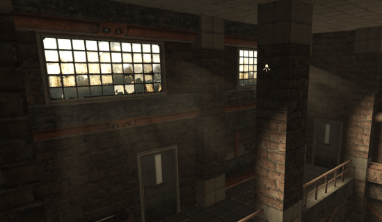
The game takes place aboard a spaceship engaged in combat with another ship. The player is responsible for issuing orders to the crew, selecting targets, distributing power to subsystems, and performing combat maneuvers, all from a first-person perspective aboard a windowless ship (after all, windows are structural weaknesses, and pretty much useless for targets more than 10 km away anyway).

Being a game that takes place in space, oxygen saturation and atmospheric pressure is obviously a constant concern, and presents several dangers to the player. I needed a way I could model this throughout the ship in a convincing, and efficient way.


What and Why?

We need a solution that handles a degree of granularity (ideally controllable by a designer), is very fast to update, and can handle the ambiguity of characters who may be transitioning between two areas. How can this be done?

Enter “Environment Probes”. A fairly common technique in computer graphics is the use of environment probes to capture and sample shading information in an area surrounding an object. Usually, these are used for reflections and lighting, allowing objects to blend between multiple static pre-baked reflections quickly rather than re-rendering a reflection at runtime. This same concept could be made to work with arbitrary volumetric data, rather than just lighting, and would cover many of the requirements of the atmosphere system!

So, let’s say that a designer can place “atmosphere probes” in the game world. Huzzah, all is well, but how can that data actually be used practically? Not only do we need to propagate values between probes, but characters need to be able to sample their environment for the current atmosphere values at their position, where there may or may not be a probe! Choosing just the nearest probe will introduce noticeable “seams” between areas, and still doesn’t easily give us the adjacency data we need to propagate values from one probe to the next!

lightprobestestscene-sourceselected

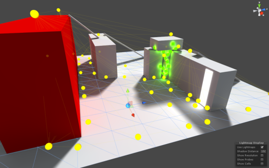
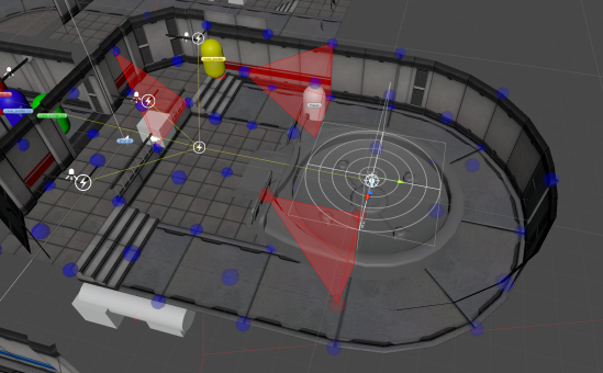
“Light Probes” in the Unity game engine. An artist can place probes around the environment (shown as yellow spheres), and have the engine pre-calculate lighting information at each sample.

Let’s look at the Unity game engine for inspiration. One of their newer rendering features is “Light Probe Groups”, which is used for lighting objects as described above. Their mechanism is actually quite clever. They build a Delaunay tetrahedralization of hand-placed probes, resulting in a mesh defining a series of tetrahedral volumes. These volumes can then be used to sample the probes at each of the four vertices, and interpolate the lighting data for the volume between them! In theory, this doesn’t have to just be for light. By simply generalizing the concept, we could theoretically place probes for any volumetric data!


Let’s Get Graphic!

I spent the majority of the time building a triangulation framework based on Bowyer-Watson point insertion. Essentially, we iteratively add in vertices one at a time, and check whether the mesh is still a valid Delaunay triangulation with each insertion. If any triangle fails to meet those constraints after the new vertex is inserted, it’s removed from the mesh, and rebuilt. This algorithm is quite simple conceptually, and works relatively quickly, making it a great choice for this system. Once this was working, it was quite simple to flesh it out in the third dimension.

Atmosphere Probes - Minimal Case.png

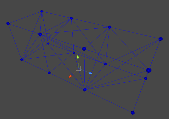
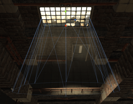
A simple Delaunay tetrahedralization of a series of “Atmosphere Probes”.

So now what? So far we have a volumetric mesh defined across a series of probe objects. What can we do with this?

Each probe has an attached “Atmosphere Probe” component which allows it to store properties about the air at that location. Pressure, oxygen saturation, temperature, you name it. This is nice in itself, but the mesh also gives us a huge amount of local information. For starters, it gives us a clear idea of which atmosphere probes are connected, and the distance between them. A few times every second, the atmosphere system will look at every edge in the graph and calculate the pressure difference between the two vertices it connects. Using the pressure difference, it will propagate atmosphere properties along that edge. We essentially treat each probe as a cell connected to its neighbors by edges, and design a fluid-dynamics simulation at a variable resolution. This means that the air at eye-level can be simulated accurately and used for all sorts of cool visual effects, while the simulation around the player’s ankles can be kept extremely coarse to avoid wasting precious iterations. By iterating through edges, we partially avoid the combinatorial explosion that would result from comparing every unique pair of graph vertices, and we can ensure that no cells will be “skipped over” when calculating flow.


Interpolation – Pretending To Know What We Don’t.

Now, how do we actually sample this data?! The probes are nice, but what if the player is standing near them, rather than on them? We want to smoothly interpolate data between these probes, so that we can sample the mesh volume at arbitrary locations. Here, we can dust off our old 2D friend, barycentric coordinates. Normally, we humans like to think in cartesian coordinates. We define a set of orthogonal directions as “Up”, “Forward”, and “Right”, and then express everything relative to those directions. “In front, and a little to the right of me…” but coordinate systems don’t always need to be this way! In theory, we could describe a location using any basis.

bary2

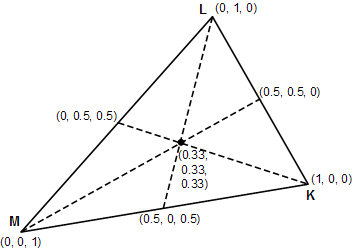
An example of a barycentric coordinate system. Each triplet shows the coordinates of that point within the triangle.

Barycentric coordinate systems define points relative to the positions of the vertices of any arbitrary simplex. So for a triangle, one could say “80% of vertex 1, 26% of vertex 2, and 53% of vertex 3”.  Conveniently, these coordinates are also normalized, meaning that a point exactly at vertex 1 will be expressed as (1,0,0). We can therefore use these coordinates for interpolation between these vertices by performing a weighted sum of the values of all the vertices of the simplex, using their corresponding component of the coordinate vector of the sample point!

So, the value of the point at the center of the diagram would be equal to

x = 0.33M + 0.33L + 0.33K

or, the average of the values of each vertex!

By calculating the barycentric coordinates of the sample point within each tetrahedron, we can determine how to average the values of each corner to find the value of that point! For our application, by knowing which tetrahedron the player is in, we can simply find the coordinates of the player in barycentric space, and do a fancy average to determine the exact atmospheric properties at his or her position! By clamping and re-normalizing coordinates, this system will also handle extrapolation, meaning that, even if the player exits the volume of the graph, the sampled properties will still be fairly accurate!

Wait… you just said “by knowing which tetrahedron the player is in…” How do we do that? Well, we can use our mesh from before to calculate even more useful information! We can determine adjacency between tetrahedra by checking if they share any faces. If two tetrahedra share three vertices, we know they are adjacent along the face formed by those three vertices… wait, it gets better… remember we had barycentric coordinates for our sample point anyway. Barycentric coordinates are normalized, and “facing inward”, so if any of our coordinates are negative, we know that the sample point must be contained within the adjacent tetrahedron opposite the vertex for which the coordinate is negative.

We essentially get to know if our sample point is in another tetrahedron for “free”, and by doing some preprocessing, we can tell exactly WHICH tetrahedron that point is within for “free”.

In the final solution, the player maintains a “current tetrahedron” reference. Whenever the player’s coordinates within that tetrahedron go negative, we update that reference to be the tetrahedron opposite the vertex with the negative coordinates. As long as the player moves smoothly and doesn’t teleport (which isn’t possible in the game I was writing this for), this reference will always be correct, and the sampler will always be aware of the tetrahedron containing the player. If the player does teleport, it will only take a few frames for the current tetrahedron reference to “walk” its way through the graph and correct itself! I also implemented some graph bounding volume checks,  so I can even create multiple separate atmosphere graphs, and have the player seamlessly walk between them!


Concavity!

The last step was ensuring that I could actually design levels the way I wanted. I quickly found that I was unable to properly design concave rooms! The tetrahedralization would build edges through walls, allowing airflow between separate rooms that should be blocked off from one-another. I didn’t want to do any geometric collision detection because that would quickly become more of a hassle, and fine-tuning doorways and staircases to allow air to flow through them is not something I wanted to bother with. Instead, I implemented “Subtraction Volumes”. Essentially a way for a level designer to hint to the graph system that a given space is impassible. Once the atmosphere graph is constructed, a post-pass runs through the tetrahedron data and removes all tetrahedra which intersect a subtraction volume. By placing them around the level, the designer can essentially cut out chunks of the graph where they see fit.

subtraction-volumes

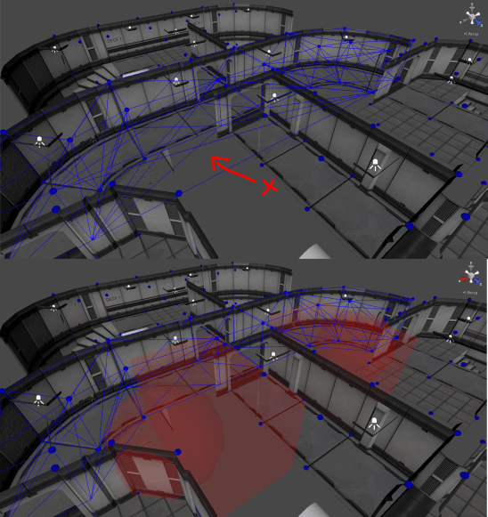
Notice in the first image there are edges spanning vertices on either side of what should be a wall. After sphere and box subtraction volumes are added, these edges are removed.


Looking Forward!

And that’s about it! Throwing that together, along with a simple custom editor in the Unity engine, I now have a great tool for representing volumetric data! In the future, I can generalize the system to represent other things, such as temperature or light-levels, and by saving the data used to calculate sample propagation, I can also determine the velocity of the air at any point for drawing cool particle effects or wind sound effects! For now, the system is finished, but who knows, maybe I’ll add more to it in the future 🙂

Ludum Dare 36

Last weekend, I spent some time working on an entry for Ludum Dare 36, an online game-jam where participants try to conceive, design, and build a game in 48 (or sometimes 72) hours! It was my first real game jam, and it ended up going pretty smoothly!

I wanted to try out some of the new features in the alpha of the upcoming version (5.5) of the Unity game engine, and this seemed like the perfect opportunity to give it a shot! I also wanted to toy around with some of the ideas and mechanics we (myself, and a group of other, very talented students) used in our school project HyperMass a few years back to see if I could work out any of the issues we were having at the time.

Without further ado, I present “Civil Service”!

CivilServicePNG
One of the things I was most excited about experimenting with was the 2D Tilemap system in Unity 5.5. Unity has always been at its core a 3D engine. Dedicated 2D features were only introduced in version 4.3… 8 years after the engine’s initial release. Quietly missing from the suite of 2D features was a “tile map” editor… a way to easily build a level from small repeated “chunks”. Version 5.5 adds this much desired feature, along with others I hadn’t even conceived of, such as “Smart Sprites”, “9 Slice Sprites”, and more!

The tile editor was exceptionally easy to use, although I encountered a number of issues with corrupted projects, and flakey features (though to be fair, I was using the alpha version of most of the tools). I found (an hour before the deadline) that release builds of tilemaps don’t have proper collision geometry defined, and characters and objects will fall right through… Luckily, my map was small and static, and I was able to throw a few large invisible boxes into the world so the player couldn’t fall through the ground!

One of the other areas I wanted to experiment in was 2D physics. Keeping the physics simulation stable was a significant issue in HyperMass, and I wanted to see if removing the third dimension could improve on it. Unity uses Box2D under the hood for 2D physics, as opposed to PhysX for normal 3D, and simplifying the gameplay would theoretically simplify the problem. It actually had a considerable impact, although some of the issues we were facing with HyperMass (particularly the simulation of a rope) were still present. I now have my own theories on how to fix it, but that’s for another post 😉

The actual Ludum Dare jam was quite a lot of fun! I was initially hesitant to join, but really enjoyed the exercise. The deadline ended up being quite tight, and I struggled to get things submitted on time, but I’m quite comfortable with how things turned out!

tsGL – Improvements

I worked a bit more on tsGL over the last few days, and managed to clean up a few things that were really bothering me! So far progress has been relatively smooth and it’s actually turning out quite well! So, what changed?

Lighting!
TSGL’s lighting code is much cleaner now, and seems to work pretty well! Lighting is broken down into a multi-pass system which allows for an arbitrary number of lights to be applied to each object. Take this scene, for example…

Composite.png

tsGL – a scene featuring three point lights. Red, blue, and white.

This scene features three realtime lights, a red light in the back left corner, a blue light behind the camera, and a white light above the scene. All of these lights are drawn as “point-lights”, meaning that they act as omnidirectional sources.

First, the scene is drawn with no lights applied. This is important to capture shader-specific details on each object, such as emissive textures, reflections, and unlit details.

Next, lights are sorted based on their “importance”. This is calculated based on distance to the object being rendered and the intensity of the light. If there’s a large, bright light shining on an object, it will be drawn first, followed by all other lights until we’ve either reached the maximum allowed number.

Then, light parameters are packed into a 4×4 matrix. This may seem odd, but it also means that all attributes of a light can be passed as a single input to the GLSL shader. This allows for a large amount of flexibility in designing shader programs, as well as the convenience of not requiring several uniform variables to be defined in each one.

The Vertex Shader calculates a set of values useful for lighting, mainly the per-vertex direction of incident light, and the attenuation of brightness over distance. These are calculated per-vertex because it reduces the number of necessary calculations significantly, and small imperfections due to interpolation over the triangle are largely imperceptible!

attenuation_withsource.png

Attenuation of one of the light in the scene, visualized in false color. Ranges from red (high intensity) to green (low intensity)

By scaling the intensity of the light with the square of the distance from the source, lights will appropriately grow dimmer as they are moved farther from an object. The diffuse component of the light is also calculated per-fragment using the typical Lambertian reflectance model, and ensures that only the “light-facing side” of objects are shaded. In the above image, the intensity of a red light throughout the scene is visualized in false color, and the final diffuse light calculation is shown on the bottom right.

Awesome, but at this point our scene is just an unlit void! How do we combine the output of each light pass into a final image?

By exploiting OpenGL blend-modes, we can produce exactly the effect we want! OpenGL allows the programmer to specify an active “blend-mode”, essentially determining how new data is written to the display buffer! This is primarily used for rendering transparent objects. A window pane for instance, would need to be rendered over top of the rest of a scene, and would mix the background color with the color of the glass itself to produce a final color! This is no different!

For these lights, the OpenGL Blend Mode is set to “additive”. This will literally add together the colors of every object drawn, which in the case of lights is just what we need. Illumination is a purely additive process, and it is impossible for a light to make things darker. Because of this, simply adding the effects of several lights together will output the illuminated scene as a whole! The best part is that it works without having to pass an array of lighting information to the shader, or arbitrarily limiting the number of available lights based on hardware! While the overhead of rendering an additional pass is non-trivial, it’s a small price to pay for the flexibility allowed by this approach.

Here, we can see the influence of each of the three lights.

lights.png

The additive passes of each of the three lights featured in the scene above. By summing together these three images, we obtain the fully illuminated scene.

At the end of the day, we end up with a process that looks like this.

  1. Clear your drawing buffers. (erases the previous frame so we have a clean slate.)
  2. Draw the darkened scene.
  3. Sort the lights based on their “importance”.
  4. Set the blend mode to “additive”.
  5. For each light in the scene (in order of importance)
    1. Draw the scene again, illuminated by the light.
  6. We’re done! Display the buffer!

This solution isn’t perfect, and more powerful techniques have been described in recent years, but given the restrictions of WebGL, I find this technique to work quite well. One feature I would like to add is for the scene to only draw objects effected by a light in the additive pass, rather than the entire scene over again. This allows us to skip any calculations that would not effect an object in some way, and may increase performance, though without further testing, it’s difficult to say for sure.

Cubemaps!
This is always a fun feature to add, because it can have incredibly apparent results. Cubemaps are essentially texture-maps that exist on all sides of a cube. Rather than sampling a single point for a color, you would sample a direction, returning the color at that “angle” within the cube. By providing an image for each face, a cubemap can be built to represent lighting information, the surrounding environment, or whatever else would require a 360 texture lookup!

cubemaps_skybox

Example of a cubemap, taken from “LearnOpenGL.com”

tsGL now supports cubemaps as a specific instance of a “texture”, and they can be mapped to materials and used identically in the engine! One of the clever uses of a cubemap is called “environment mapping”, which essentially boils down to emulating reflection by looking up the color of the surrounding area in a precomputed texture. This is far more efficient than actually computing reflections dynamically, and plays much more nicely within the paradigms of traditional computer graphics! Here’s a quick example of an environment-mapped torus running in tsGL!

yakf0.gif

An environment-mapped torus, showcasing efficient reflection.

Now that cubemaps are supported, it’s also possible to make reflective and refractive materials efficiently, so shader programs can be made much more interesting within the confines of the engine!

Render Textures
Another nifty feature is the addition of render textures! By essentially binding a “camera” object to a texture, it is possible to render the scene into that texture, instead of onto the screen! This texture can then be used like any other anywhere in the drawing process, which means it’s possible to do things like draw a realtime security camera monitor in the scene, or have a mirror with realtime reflections! This can get quite costly, so it is best used sparingly, but the addition of this feature opens the door to a wide variety of other cool effects!

With the addition of both cubemaps and render textures, I hope to get shadow-mapping working in the near future, which would allow objects to appropriately cast shadows when illuminated in the scene, which was previously infeasible!

And now, the boring stuff – HTML
The custom HTML tag system has been improved immensely, and now makes much more sense. Entity tags may now be nested to define object hierarchies, and arbitrary parameters can be provided as child-tags, rather than attributes. This generally makes the scene documents far more legible, and makes adding new features in the future much easier.

Here’s a “camera” object, for example.

<tsgl-entity id=”main_camera”>
<tsgl-component type=”camera”>
<tsgl-property type=”number” name=”fov” value=”80″></tsgl-property>
<tsgl-property type=”number” name=”aspect” value=”1.6″></tsgl-property>
</tsgl-component>
<tsgl-component type=”transform”>
<tsgl-property type=”vector” name=”position” value=”0 2 0″></tsgl-property>
</tsgl-component>
</tsgl-entity>

Previously, the camera parameters would have been crammed into a single tag’s attributes, making it much more difficult to read, and much more verbose. With the addition of tsgl-property tags, attributes of each scene entity can now be specified within the entity’s definition, so all of those nice editor features like code-folding can now be exploited!

This part isn’t exactly fun compared to the rendering tests earlier, but it certainly helps when attempting to define a scene, and add new features!

That’s all for now! In the meantime, you can check out the very messy and very unstable, tsGL on GitHub if you want to try it for yourself, or experiment with new features!

tsGL – An Experiment in WebGL

dragon_turntable

For quite some time now, I’ve been extremely interested in WebGL. Realtime, hardware-accelerated rendering embedded directly in a web-page? Sounds like a fantastic proposition. I’ve dabbled quite a bit in desktop OpenGL and have grown to like it, despite its numerous… quirks… so it seemed only natural to jump head-first into WebGL and have a look around!

So, WebGL!
I was quite surprised by WebGL’s ease of use! Apart from browser compatibility (which is growing better by the week!) WebGL was relatively simple to set up. Initialize an HTML canvas context, and go to town! The rendering pipeline is nearly identical to OpenGL ES, and supports the majority of the same features as well! If you have any knowledge of desktop OpenGL, the Zero-To-Triangle time of WebGL should only be an hour or so!

Unfortunately, WebGL must be extremely compatible if it is to be deployed to popular web-browsers. This means that it has to run on pretty much anything with a graphics processor, and can’t rely on the user having access to the latest and greatest technologies! For instance, when writing the first draft of my lighting code, I attempted to implement a deferred rendering pipeline, but quickly discovered that multi-target rendering isn’t supported in many WebGL instances, and so I had to fall back to the more traditional forward rendering pipeline, but it works nonetheless!

dabrovic_pan

A textured scene featuring two point lights, and an ambient light.

Enter TypeScript!
I’ve never been particularly fond of Javascript. It’s actually quite a powerful language, but I’ve always been uncomfortable with the syntax it employs. This, combined with the lack of concrete typing can make it quite difficult to debug, and quite early on I encountered some issues with trying to multiply a matrix by undefined. By the time I had gotten most of my 3D math working, I had spent a few hours trying to find the source of some ugly, silent failures, and had decided that something needed to be done.

I was recommended TypeScript early in the life of the project, and was immediately drawn to it. TypeScript is a superset of Javascript which employs compile-time type checking, and a more familiar syntax. Best of all, it is compiled to standard minified Javascript, meaning it is perfectly compatible with all existing browsers! With minimal setup, I was able to quickly convert my existing code to TypeScript and be on my way! Now, when I attempt to take the cross product of a vector, and “Hello World”, I get a nice error in the Javascript console, instead of silent refusal.

Rather than defining an object prototype traditionally,

var MyClass = ( function() {
function MyClass( value ) {
this.property = value;
}
this.prototype.method = function () {
alert( this.property );
};
return MyClass;
})();

One can just specify a class.

class MyClass {
property : string;
constructor( value : string ) {
this.property = value;
}
method () {
alert( this.property );
}
}

This seems like a small difference, and honestly it doesn’t matter very much which method you use, but notice that property is specified to be of type string. If I were to construct an instance of MyClass and attempt to pass an integer constant, a compiler error would be thrown, indicating to me that MyClass instead requires a string. This does not effect the final Javascript, but reduces the chance of making a mistake while writing code significantly, and makes it much easier to keep your thoughts straight when coming back to a project after a few days.

Web-Components!
When trying to decide on how to represent asset metadata, I eventually drafted a variant on XML, which would allow for simple asset and object hierarchies to be defined in “scenes” that could be loaded into the engine as needed. It only took a few seconds before I realized what I had just described was essentially HTML. From here I looked into the concept of “Web-Components” a set of prototype systems that would allow for more interesting UI and DOM interactions in modern web browsers. One of the shiny new features proposed is custom HTMLElements, which allow developers to define their own HTML tags, and associated Javascript handlers. With Google Chrome supporting these fun new features, I quickly took advantage.

Now, tsGL scenes can be defined directly in the HTML document. Asset tags can be inserted to tell the engine where to find certain textures, models, and shaders. Here, we initialize a shader called “my-shader”, load an OBJ file as a mesh, and construct a material referencing a texture, and a uniform “shininess” property.

<tsgl-shader id=”my-shader” vert-src=”/shaders/test.vert” frag-src=”/shaders/test.frag”></tsgl-shader>

<tsgl-mesh id=”my-mesh” src=”/models/dragon.obj”></tsgl-mesh>

<tsgl-material id=”my-material” shader=”my-shader”>
<tsgl-texture name=”uMainTex” src=”/textures/marble.png”></tsgl-texture>
<tsgl-property name=”uShininess” value=”48″></tsgl-property>
</tsgl-material>

We can also specify our objects in the scene this way! Here, we construct a scene with an instance of the “renderer” system, a camera, and a renderable entity!

<tsgl-scene id=”scene1″>
<tsgl-system type=”renderer”></tsgl-system>

<tsgl-entity>
<tsgl-component type=”camera”></tsgl-component>
<tsgl-component type=”transform” x=”0″ y=”0″ z=”1″></tsgl-component>
</tsgl-entity>

<tsgl-entity id=”dragon”>
<tsgl-component type=”transform” x=”0″ y=”0″ z=”0″></tsgl-component>
<tsgl-component type=”renderable” mesh=”mesh_dragon” material=”mat_dragon”></tsgl-component>
</tsgl-entity>
</tsgl-scene>

Entities can also be fetched directly from the document, and manipulated via Javascript! Using document.getElementById(), it is possible to obtain a reference to an entity defined this way, and update its components! While my code is still far from production-ready, I quite like this method! New scenes can be loaded asynchronously via Ajax, generated from web-servers on the fly, or just inserted into an HTML document as-is!

Future Goals
I wanted tsGL to be a platform on which to experiment with new web-technologies, and rendering concepts, so I built it to be as flexible as possible. The engine is broken into a number of discreet parts which operate independently, allowing for the addition of cool new features like rigidbody physics, a scripting interface, or whatever else I want in the future! At the moment, the project is quite trivial, but I’m hoping to expand it, test it, and optimize it in the near future.

At the moment, things are a little rough around the edges. Assets are loaded asynchronously, and the main context just sits and complains until they appear. Rendering and updating operate on different intervals, so the display buffer tears like tissue paper. OpenGL is forced to make FAR more context switches than necessary, and my file parsers don’t cover the full format spec, but all in all, I’m quite proud of what I’ve managed to crank out in only ten or so hours of work!

If you’d like to check out tsGL for yourself, you can download it from my GitHub page!

Building a Mobile Environment for Unity

Environments are incredibly important in games. Whether it’s a photo-realistic depiction of your favorite city or an abstract void of shapes and color, environments help set the mood of a game. Lighting, color, and ambient sounds are all instrumental in the creation of an immersive and convincing world. They can be used to subtly guide the players to their objective (ever noticed how the unlocked door is almost always illuminated, while locked doors are in shadow?), or even provide contextual clues about the history of a world. I’ve always been fascinated with environments and, while I wouldn’t exactly consider myself an environment artist, I’ve spent some time working on quite a few.

Mobile games are a challenge. Smartphones keep getting faster, but as processor speeds rise, so too do the expectations of the player. Mobile environments now need to look fleshed out and detailed, while still playing at a decent frame-rate. You need to fake the things you can’t render, and you need to design around the things you can’t fake.

So! With that said, let’s take a look at a Unity environment.

This runs pretty well on mobile! It’s capped at 60 frames per second on my iPhone 5s (Video frame-rate is lower due to the video capture), and runs even faster on newer models. So, what does our scene look like? How can we take advantage of Unity 5’s built in optimizations? Let’s start with the basics.

Geometry:


This level consists of a few meshes, instanced dozens of times. I initially planned the environment to work as a “kit”, a single set containing a number of smaller meshes to be used in different ways. All of the meshes in an individual kit share the same visual theme so that they can be used interchangeably. This scene, for example, is a single kit called env_kit_factory. One of the advantages of this approach is total modularity. Building new environments can be done entirely in the editor, and incredibly quickly. This is not only faster than having your artists sculpt huge pieces of geometry, but also allows you to exploit the benefits of Unity’s Prefab system. Changing a material in the prefab will automatically update all instances in the scene, without having to manually replace all instances in a large level.

kit_demo

Every asset used in the “factory” environment.

The modularity of this geometry is useful for level construction as well. By building assets that fit together, maintain a consistent visual aesthetic, and don’t contain recognizable writing or symbols, assets can be combined in unique ways and often in configurations the artist never intended. Here’s an example. This piece of floor trim can be used as a supporting column, a windowsill, a loading dock, or whatever else you can come up with, and it looks reasonably decent.

asset reuse.gif

This wouldn’t work quite so well if the trim were modeled as part of the wall. The wall wouldn’t tile vertically for one thing, far more varieties of walls would be necessary to break up the repetition, and it would generally just be harder to work with. Allow small detail objects and decals to provide unique markers that level designers can place anywhere, instead of trying to build a hundred different versions of the same brick wall.

I used decal meshes extensively. These are essentially “stickers” that can be placed in your scene to break up the monotony of a tiled surface, and provide much more specific details than you may want to build into a modular set-piece.

leaky pipes.png

Leaky pipe decals used to disguise the seams between the pipes and the wall.

Here, we can see a set of copper pipes, and apparent water damage down the wall where they meet. This is achieved entirely with decals, and required little to no extra work, but makes the environment feel a bit more cohesive. These decals also introduce visually unique patterns that help draw the eye away from the otherwise repetitious brick pattern.

crushed boxes.png

Decals can be used to hint at purpose and story as well as provide interesting visuals. Here we can see more water damage, and this time not just from leaking pipes. These cardboard boxes look haphazard and temporary, but the damp paper and thick dust allude to years of neglect. Subtleties like this can really make an environment feel more complete, and with careful thought can be implemented without too much additional work on the part of the artist.

Textures:


I took great care when designing the factory kit to reuse textures as much as I could. For one thing, it’s an interesting challenge, but more importantly, it allows us to take advantage of Unity’s built in optimizations. All textures are at 1024 x 1024 resolution, and function as large atlases for significant portions of the environment.

textures.png

All textures used in the scene (not including secondary maps)

Here we can see that all walls, floors, bits of concrete and metals share the same texture and material setup. The advantage is twofold. First, it helps maintain a consistent aesthetic. Every brick wall in the entire scene will be colored the same, and minor changes to that texture will be carried over to the rest of the kit. This is much easier than trying to keep a dozen different brick textures in sync, and if done well can still look great.

The second advantage is based in rendering performance. Modern graphics hardware is incredibly good at drawing things. Massive parallelism is designed directly into GPUs, and it works extremely well for vertex and fragment processing. What graphics cards aren’t good at is preparing to draw things. Let’s look at how a typical model might be rendered.

  1. LOAD – ModelView matrix to local memory
  2. LOAD – Projection matrix to local memory
  3. LOAD – Albedo texture to local memory
  4. LOAD – Vertex attributes to local memory
  5. USE – Albedo texture
  6. USE – Vertex attributes
  7. RUN – Vertex shader
  8. RUN – Fragment shader
  9. RASTERIZE

Wow, even for a high-level overview that’s surprisingly complex! Every time you send data to the graphics card, that data has to be copied over from main memory to video memory. This is an extremely slow operation when compared to actually processing fragments and writing them to the framebuffer! Luckily graphics specifications like OpenGL and DirectX do not reset the state of the hardware whenever drawing is finished. If I tell the API to “use texture 5”, it will (or should, at least) keep using texture 5 until I tell it to stop. What this means is that we can organize our drawing operations in such a way that we minimize the number of times we need to copy data back and forth. If we’re drawing 100 objects that all use Texture 5, we can just set Texture 5 once and draw all 100 objects, instead of naively and redundantly setting it 99 additional times.

scene_rendering.gif

A breakdown of the batches used when rendering the scene.

The Unity game engine is actually pretty good at this! Objects that share textures will be grouped together in batches to minimize state changes, and in some cases can dramatically improve performance. There are several hundred objects in this scene, but only around 30 GPU state changes. Stepping through the Unity “Frame Debugger”, we can see that  enormous portions of the scene are rendered as one large chunk, which keeps the state switching to a minimum, and allows the graphics processor to do its thing with minimal interruption!

Lighting:


Lighting is extremely important to convey the look and feel you’re trying to get across in your scene. Unfortunately, it is also one of the most computationally expensive aspects of rendering a scene.

To dust off one of my favorite idioms about optimization, “The fastest code is code that never runs at all”. We’d all love a thousand dynamic lights fluttering around our scene, but we’re restricted in what we can do, especially on a mobile device. To circumvent the performance issues associated with real-time lighting, all lighting in the scene is either “baked or faked”.

A common technique, as old as realtime rendering itself, is the concept of a lightmap. If the lighting in a scene never changes, then there’s no reason to be performing extremely expensive lighting calculations dozens of times a second! That rock is sitting under a lamp, and it’s not going to get any less bright as long as it stays there, and the lamp remains on! This is the basic idea behind lightmapping. We can calculate the lighting on every surface in our scene once before the program is even running, and then just use the results of those calculations in the future! We “Bake” the lighting into a texture map, and pass it along with all of the others when we render our scene.

lightmapping.png

The lightmaps used in the factory scene.

Lightmapping has its disadvantages. The resolution of the baked lighting often isn’t as good as a realtime solution by the nature of it operating per-texel, rather than per-pixel, and more complex effects like specular highlights and reflections are tricky if not impossible, but that’s a small price to pay for the performance gain of baked lighting.

I wanted the scene to feel stuffy and old, so I decided that the air in the room should appear to be filled with dust. Unfortunately, this means that light needs to scatter convincingly, and subtly. True volumetric lighting has only recently become feasible in a realtime context, but it is still far from simple on a mobile device! To get around this, I faked the symptoms with some of the oldest tricks in the book.

fog.gif

Comparison of the scene with fog enabled and disabled.

First, I applied a “fog” effect. This technique, commonly seen in old N64 and PS1 games is often used to disguise the far clip plane of the camera, and add a greater sense of depth to the scene by fading to a solid color as objects approach a certain threshold distance. I liked the look of this effect when applied to the scene, as it makes the air feel thicker than normal, and gives it a hazy feel.

light shafts.png

Next, I built fake “lightshafts”. A common technique used to depict light diffusing through dust or smoke. These may look fancy, but it’s really just a mesh with a custom shader applied.

lightshaft_mesh.png

By scrolling the color of a texture slowly on one axis, while keeping its alpha channel fixed, it’s possible to make the shafts of light appear to waver slightly and gently shift between multiple shapes, exactly as if something in the air were slowly moving past the light source! This effect essentially boils down to a glorified particle effect, but it is quite convincing when used in conjunction with fog!

Wrapping Up:


  • Game environments are extremely difficult, and I’ve still got a lot to learn, but I hope some of these tips can help others when designing scenes! Remember…
  • Reuse and repurpose assets. A little bit of thought can go a long way, so plan out your assets before getting started, and you’ll find it much easier to work on later on.
  • Build environments modularly. By assembling assets into kits, not only will your level designers thank you, but building new environments becomes trivially easy.
  • Atlas textures. On mobile devices, texture memory is limited, and GPU context switches can be extremely slow. Try to consolidate your textures as much as possible to reduce overhead.
  • Bake lightmaps. The performance gain is enormous, and with the right additions, you can make something very convincing!

Thanks for sticking with me for the duration of this article, and to everyone out there building fantastic Unity games, keep up the good work!

-Andrew

Heatwave

A few years back I worked on a Unity engine game for a school project, called “Distortion”. In this game, the player has a pair of scifi-magic gloves that allows him or her to bend space. I ended up writing some really neat visual effects for the game, but it never really went anywhere. This afternoon I found a question from a fellow Unity developer, asking how to make “heat ripple” effects for a jet engine, and I decided to clean up the visual effects and package them into a neat project so that others could use it too!

And so, Heatwave was born.

heatwave_flame_demo_gif

Heatwave is a post-processing effect for the Unity game engine that takes advantage of multi-camera rendering to make cool distortion effects easy! It does this by rendering a full-screen normal map in the scene using a specialized shader. This shader will render particle effects, UI elements, or overlay graphics together into a single map that is then used to calculate refractions!

heatwave_normalBuffer

The main render target is blitted to a fullscreen quad, and distorted by offsetting the UV coordinates during the copy based on the refraction vector calculated using the normal map, resulting in a nice realtime psuedo-refraction!

There are a few issues with this method, mainly that it doesn’t calculate “true” refractions. The effect is meant to look nice more than to make accurate calculations, so cool effects like refracting light around corners and computing caustics aren’t possible. The advantage however is that the effect operates in screen-space. The time required to render distortion is constant, and the cost of adding additional distortion sources is near zero, making it perfect for games, and situations where a large number of sources will be messing with light!

I’ve made a small asset-package so other Unity developers can download the sources and use them!

You can find the project on Github here!

Object-Oriented Programming and Unity – Part 3

Recently, I’ve read complaints from a lot of Unity developers about how the engine doesn’t provide adequate support for object-oriented programming and design, with even very experienced developers running into this issue! In my opinion, this problem doesn’t really exist, and I feel as though most of the issues developers are facing stems from some fundamental misconceptions about how the engine is designed, so I’d like to take a moment to try and shed some light on the subject.

This is part 3 of a multi-part post. If you haven’t read part 2. I recommend you read it here.


Wrapping Up

– Unity is an incredibly flexible game engine.

Its scripting engine supports nearly all of the .NET framework, and can be made to do just about anything. Inheritance hierarchies, generic classes and functions, interfaces, reflection, they all work just fine. That being said, there are a large number of restrictions placed on us as developers. Many of the engine’s core components may not be modified, and nearly all of the classes and functions exposed in the Unity API are completely sealed. While this may seem annoying at first, it’s important to take a step back and think of what the engine is actually doing when you use those classes, and the damage that can be caused by overriding a method.

– It takes some getting used to.

Many of the restrictions of the scripting API require developers to organize code in ways that may not seem intuitive. We often get frustrated when our first set of ideas don’t work, and for many people, the immediately apparent solution that doesn’t seem to be possible “should be possible”. Keep in mind that you’re not working in a vacuum. The engine itself has a huge job to do, and considerations must be made to work both in and around it. When working within the Unity engine, some design patterns behave very well, and others don’t. The problem isn’t that the engine is broken or incomplete, but the team behind Unity decided on an architecture that may not mesh well with your code depending on your design. Take a step back, and think of what you want to do as well as what the engine wants to do.

Quick Recap

  1. Don’t build hierarchies, build composite objects.
  2. Don’t extend types, encapsulate them.
  3. Don’t program in a vacuum, consider what the engine needs to do.
  4. If you find the need to subclass a GameObject or Component, consider alternative designs.

Thank you for sticking with me and reading this article! I hope I managed to shed some light on the inner-workings of the Unity engine’s basic architecture, and make things a bit more clear. If you have any questions, feel free to contact me!

– Andrew Gotow

Object-Oriented Programming and Unity – Part 2

Recently, I’ve read complaints from a lot of Unity developers about how the engine doesn’t provide adequate support for object-oriented programming and design, with even very experienced developers running into this issue! In my opinion, this problem doesn’t really exist, and I feel as though most of the issues developers are facing stems from some fundamental misconceptions about how the engine is designed, so I’d like to take a moment to try and shed some light on the subject.

This is part 2 of a multi-part post. If you haven’t read part 1, I recommend you read it here.


Inheritance ≠ Object Oriented Programming.

OOP is a programming paradigm designed to make the design and use of a system more modular, and more intuitive to a developer. By grouping related data into objects, it can be treated as a unified collection, rather than a set of scattered elements, and can be added and removed from an architecture in a generic, and nonintrusive way.

One of the key concepts behind this is inheritance, allowing us to define “subclasses” of a class in order to extend its functionality. You can think of subclasses as a specific implementation of a more generic “parent” class, like how dogs and cats were both specific forms of animals in the previous inheritance example.

Inheritance is a large portion of traditional object-oriented programming, but the two are NOT synonymous. Object-oriented programming is merely a concept. The principles behind the Object-Oriented paradigm are equally valid with or without formal class inheritance, and can even be expressed in traditionally “non object-oriented” languages, such as C!

So why is Unity often criticized as being non-OO?

The Unity game engine maintains very tight control over its inheritance hierarchies. Developers are not allowed to create their own subclasses of many of the core components, and for good reason! Take “Colliders” for example. Colliders define the shape of an object for the physics system so that it can quickly and efficiently simulate physical interactions in the game world. Simulating physics is incredibly expensive, and as a result many shortcuts have been taken to ensure that your game runs as smoothly as possible. In order to minimize the workload, the physics system, (in Unity’s case, PhysX by NVidia), has been optimized to only process collisions on a set number of primitive shapes. If the developer were to add a new, non-standard shape, the PhysX would have no idea how to handle it. In order to prevent this, the kind folks at Unity have made Collider a sealed class, which can’t be extended.

Wait, then what can we modify?

Let’s look at the component hierarchy in Unity.

unity component hierarchy fixed

Yep, that’s it. The only portion of the Unity component hierarchy you are allowed to modify is “MonoBehaviour”.

GameObjects contain a set of attached “Behaviours”, commonly referred to as Components (while it is confusing within the context of the class hierarchy, it makes more sense when considering the exposed portions of the ECS architecture). Each of these defines a set of data and functions required by the constructed entity, and are operated on by Systems which are hidden from the developer. Each System is responsible manipulating a small subset of behaviours, for instance the physics System operates on Rigidbody and Collider components. With this in mind, how can developers create their own scripts and behaviors?

The Unity team had to come up with a solution that allowed all built-in components to be pre-compiled and manipulated without exposing any of the underlying architecture. Developers also couldn’t be allowed to create their own Systems, as they would need to make significant changes to the engine itself in order to incorporate their code into their application. Clearly, a generic System needed to be designed to allow runtime execution of unknown code. This is exactly what a MonoBehaviour does. MonoBehaviours are behaviours containing tiny Mono executables compiled while the editor is running. Much like the physics System, a MonoBehaviour System is managed by the editor, and is responsible for updating every MonoBehaviour in the game as it runs, periodically calling functions accessible to the scripting interface, such as “Start”, and “Update”. When a developer writes a script, it’s compiled to a MonoBehaviour, and is then operated on just like any other component! By adding a new System, and exposing a scripting interface, developers are now able to create nearly anything they want, without requiring any changes to the engine code, and still running with the efficiency of a compiled language, brilliant! (Keep in mind that the actual editor implementation is most likely more complex than this, however I feel that this cursory explanation is enough to effectively utilize the engine.)

Well, that’s all well and good… but what if some of my behaviours need to inherit from others?

Inheritance hierarchies work just fine within the context of MonoBehaviours! If we really needed to, we could make our own components, and have them inherit from one another, as long as the root class inherits from MonoBehaviour. This can be useful in some situations, for instance if we had a set of scripts which were dependent on another, we could provide all necessary functionality in a base class, and then override it for more specific purposes in a subclass. In this example, our MovementScript may depend on a control script in order to query input. We can subclass a generic control script in order to create more specialized inputs, or even simple AI, without changing our MovementScript.

Unity Monobehaviour Inheritance

The more experienced among you may recognize that, for this problem, perhaps implementing an interface would provide a more elegant solution than subclassing our control script. Well, we can do that too!

public interface MyInterface {}
public class MyScript : MonoBehaviour, MyInterface {}

There’s nothing special about MonoBehaviours. They’re just a very clever implementation of existing programming techniques!

MonoBehaviours sound really cool, but I have data I don’t want attached to a GameObject!

Well, then don’t use a MonoBehaviour! MonoBehaviors exist to allow developers to attach their scripts to GameObjects as a component, but not all of our code needs to inherit from it! If we need a class to represent some data, we can just define a class in a source file like you would in any traditional development environment.

using UnityEngine;

public class MyData {
    const int kConstant = 10;

    private int foo = 5;
    public int bar = 10;

    public Vector3 fooBar = new Vector3( 1, 2, 3 );
}

Now that this class is defined, we can use it anywhere we want, including in other classes, and our MonoBehaviours!

using UnityEngine;

public class MyMonoBehaviour : MonoBehaviour {

    private MyData data;

    void Start () {
        data = new MyData();

        data.fooBar = new Vector3( -1, -2, -3 );
    }
}

Also keep in mind that the entirety of the .NET framework (Version 2.0 at the time of this article) is accessible at any time. You can serialize your objects to JSON files, send them to a web-server, and forward the response through a socket if you need to. Just because Unity doesn’t implement a some feature, doesn’t mean it can’t be done within the engine.


This post demonstrates a few examples of how data can be handled outside of the MonoBehaviour system. This post is continued in Part 3, where we will recap a few points, and conclude this article.

PART 3 =>

Object-Oriented Programming and Unity – Part 1

Recently, I’ve read complaints from a lot of Unity developers about how the engine doesn’t provide adequate support for object-oriented programming and design, with even very experienced developers running into this issue! In my opinion, this problem doesn’t really exist, and I feel as though most of the issues developers are facing stems from some fundamental misconceptions about how the engine is designed, so I’d like to take a moment to try and shed some light on the subject.


Unity Engine Architecture, and Composition vs. Inheritance.

The Unity game engine represents the “physical” world of your program using an Entity Component System architecture. Each “object”, be it a character, a weapon, or a piece of the environment, is represented by an entity (referred to as GameObjects in the Unity engine). These entities do nothing on their own, but act as containers into which many components are placed. Each component represents a functional unit, and dictates a specific subset of the behavior of our object. Lastly, Systems act as a higher-level control system, which act on entities to update the state of their components. ECS has become increasingly popular in the game development world, as it provides some key advantages over more traditional architectures.

  1. Components are completely reusable, even across objects with dramatically different behaviors.
  2. Components provide near infinite extensibility, allowing new behaviors to be added to the game without touching any of the existing code.
  3. Components can be added and removed at run-time, allowing for the behavior of objects to change while the application is running, without any significant effort.

The entity component architecture embodies the principle of composition over inheritance, a relatively new programming paradigm which favors the structure and composition of an object over a hierarchy of inheritance. This is especially helpful when building a large application like a game, which requires many things to share large amounts of very similar code, while still being different in sometimes hundreds of ways.

Let’s look at an example.

Imagine we have a client who wants us to write a game about animals! Let’s represent a dog, and a cat in our code. The immediately intuitive solution would be to make a superclass called “Animal”, to contain the commonalities of both cats and dogs.

Animal_inheritance_corrected

That’s fantastic! Look, we just saved having to duplicate all of the code required to give our animal ears, legs, and a tail by using inheritance! This works really well until your client asks you to add a squid. Ok! Let’s add it to our animal class! Unfortunately, squids don’t have ears, or really much of a tail. They’ve also got 10 limbs, so our class hierarchy will have to change a bit. Let’s add another superclass, this time separating cats and dogs into their own group.

Animal_inheritance_2_corrected

Ok, there we go. Now the things shared across all animals can be separated out, and our dog and cat can still share legs, a tail, and ears! Our client liked the squid so much, he wants us to put in other ocean animals too! He asked us to put in a fish! Well, both fish and squid swim and have fins, so it would make sense to put them together… but fish also have a tail, and right now, a tail is defined as a part of mammals!

Animal_inheritance_3_corrected

Oh no! Suddenly, our hierarchy doesn’t look too good! While it makes the most sense to put animals into groups based on their defining characteristics, sometimes characteristics will be shared across multiple different subtrees, and we can’t inherit them from a parent!

Composition to the rescue!

Rather than defining our animals as a hierarchy of increasingly specific features, we can define them as individuals, composed of independent component parts.

Animal_composition

Notice that we still don’t have to duplicate any of our code for shared features! Attributes like legs are still shared between dogs, cats, and squids, but we don’t have to worry about where fish fit into the picture! This also means that we can add any animal component we want, without even touching unrelated animals! If we wanted to add a “teeth” component, we could attach it to dogs, cats, and (some) fish to provide new functionality, and wouldn’t even need to open the file for squids!

This model also allows us to add components at run-time to change functionality. Let’s say we have a robot. This robot normally attacks the player on sight, and does generally evil things. It’s pretty complicated too! The robot can move around the game, use a weapon, open doors, and more! What happens when our player hacks this robot character to be a good-guy? We could make a second type of robot, which can do everything the evil robot can, OR we can remove the “robot_AI_evil” component, and replace it with “robot_AI_good”. With the AI component replaced, our robot can help us and still do everything the evil robot could. If it’s well designed, it could even display more complex behavior, and use abilities it typically would use against the player to help defend against other robots!

Know that inheritance isn’t a bad thing, in fact we to use it to define our body part components, but understand that in some situations, other paradigms may be more useful!


This post provides a cursory look at the Unity engine’s general world representation, as well as a cursory look at some of the potential benefits of the “composition over inheritance” principle.
This post is continued in Part 2, where we will look at MonoBehaviours, and their role in the Unity engine.

PART 2 =>

Unfinished Projects

Whenever I have an idea, I like to run with it. Most of them never really get off the ground, but I’ve learned a lot in the process. I decided to make a quick video of some of these projects and what they’ve taught me.


There are no bad ideas, and if seen through, they can teach you things you’d never expect! Often the best way to learn is through experience!