The programmable rendering pipeline is perhaps one of the largest advances in the history of realtime computer graphics. Before its introduction, graphics libraries like OpenGL and DirectX were limited to the “fixed function pipeline”, a programmer would shove in geometric data, and the application would draw it however it saw fit. Developers had little to no control over the output of their application beyond a few “render mode” settings. This was fine for rendering relatively simple scenes, solid objects, and simplistic lighting, but as visual fidelity increased and hardware become more powerful it quickly became necessary to allow for a more customizable rendering.
The process of rendering a 3D object in the modern programmable pipeline is typically broken down into a number of steps. Data is copied into fast-access graphics memory, then transformed through a series of stages before the graphics hardware eventually rasterizes that data to the display. In its most basic form, there are two of these stages the developer can customize. The “Vertex Program” manipulates data on a per-vertex level, such as positions and texture coordinates, before handing the results on to the “Fragment Program”, which is responsible for determining the properties of a given fragment (like a pixel containing more than just color information). The addition of just these two stages opened the floodgates for interesting visual effects. Approximating reflections for metallic objects, cel-shading effects for cartoon characters, and more! Since then, even more optional stages have been inserted into the pipeline for an even greater variety of effects.
I’ve spent a considerable amount of time experimenting with vertex and fragment programs in the past, but this week I decided to spend a few hours working with the other, less common stages, mainly “Geometry Programs”. Geometry programs are a more recent innovation, and have only began to see extensive use in the last decade or so. They essentially allow developers to not only modify vertex data as it’s received, but to construct entirely new vertices based on the input primitives (triangles, quads, etc.) As you can easily imagine, this presents incredible potential for new effects, and is something I personally would like to become more experienced with.
In four or five hours, I managed to write a relatively complex effect, and the rest of this post will detail, at a high level, what I did to achieve it.

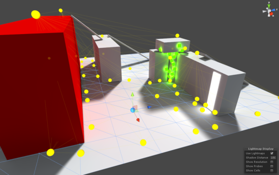
Procedurally generated geometry for ivy growing on a simple building.
This is my procedural Ivy shader. It is a relatively simple two-pass effect which will apply artist-configurable ivy to any surface. What sets this effect apart from those I’ve written in the past is that it actually constructs new geometry to add 3D leaves to the surface extremely efficiently.
One of the major technical issues when it comes to rendering things like foliage is that the level of geometric detail required to accurately represent leaves is quite high. While a digital environment artist could use a 3D modeling program to add in hundreds of individual leaves, this is not necessarily a good use of their time. Furthermore, it quickly becomes unmaintainable if anyone decides that the position, density, or style of foliage should change in the future. I don’t know about you, but I don’t want to be the one to have to tell a team of environment artists that all of the ivy in an entire game needs to be slightly different. In this situation, the key is to work smarter, not harder. While procedural art is often controversial in the game industry, I think most developers would agree that artist-directed procedural techniques are an invaluable tool.

First and foremost, my foliage effect is composed of two separate rendering passes. First, a triplanar-mapped base texture is blended onto the object based on the desired density of the ivy. This helps to make the foliage feel much more dense, and helps to hide the seams where the leaves meet the base geometry.
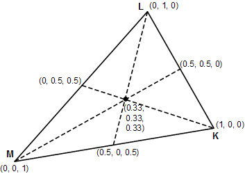
Next in a second rendering pass, the geometry program transforms every input triangle into a set of quads lying on that triangle with a uniform, psuedo-random distribution. First, it is necessary to determine the number of leaf quads to generate. In order to maintain a consistent density of leaf geometry, the surface area of the triangle is calculated quickly using the “half cross-product formula”, and is then multiplied by the desired number of leaves per square meter of surface area. Then, for each of these leaves, a random sample point on the triangle is picked, and a triangle strip is emitted. It does this by sampling a noise function seeded with the world-space centroid of the triangle and the index of the leaf quad being generated. These noise values are then used to generate barycentric coordinates, which in turn are used to interpolate the position and normal of the triangle at that point, essentially returning a random world-space position and its corresponding normal vector.
Now, all that’s needed is to determine the orientation of the leaf, and output the correct triangle-strip primitive. Even this is relatively simple. By using the world-space surface normal and world “up” vector, a simple “change of vector basis” matrix is constructed. Combining this with a slightly randomized scale factor, and a small offset to orientation (to add greater variety to patches of leaves), we can transform normalized quad vertices into the exact world-space positions we want for our leaves!
...

// Defines a unit-size square quad with its base at the origin. doing
// this allows for very easy scaling and positioning in the next steps.
static const float3 quadVertices[4] = {
   float3(-0.5, 0.0, 0.0),
   float3( 0.5, 0.0, 0.0),
   float3(-0.5, 0.0, 1.0),
   float3( 0.5, 0.0, 1.0)
};

...

// IN THE GEOMETRY SHADER
// Change of basis matrix converts from XYZ space to leaf-space
float3x3 leafBasis = float3x3(
   leafX.x, leafY.x, leafZ.x,
   leafX.y, leafY.y, leafZ.y,
   leafX.z, leafY.z, leafZ.z
);

// constructs a random rotation matrix from Euler angles in the range
// (-10,10) using wPos as a seed value.
float3x3 leafJitter = randomRotationMatrix(wPos, 10);

// Combine the basis matrix by the random rotation matrix to get the
// complete leaf transformation. Note, we could use a 4x4 matrix here
// and incorporate the translation as well, but it's easier to just add
// the world position as an offset in the final step.
float3x3 leafMatrix = mul(leafBasis, leafJitter);

// lastly, we can just output four vertices in a triangle strip
// to form a simple quad, and we'll be on our merry way.
for ( int i = 0; i < 4; i ++ ) {
   FS_INPUT v;
   v.vertex = UnityWorldToClipPos(
      float4( mul(leafMatrix, quadVertices[i] * scale), 1) + wPos
   );
   triStream.Append(v);
}
At this point, the meat of the work is done! We’ve got a geometry shader outputting quads on our surface. The last thing needed is to texture them, and it works!
Configuration!
I briefly touched on artist-configurable effects in the introduction, and I’d like to quickly address that too. I opted to go with the simplest solution I could think of, and it ended up being incredibly effective.

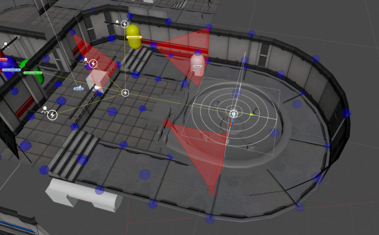
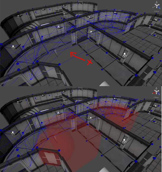
Configuring procedural geometry using painted vertex weights.
The density and location of ivy is controlled through painted vertex-colors. This allows artists to simply paint sections of their model they would like to be covered in foliage, and the shader will use this to weight the density and distribution of the procedural geometry. This way, an environment artist could use the tools they’re familiar with to quickly sketch out what parts of a model they would like to be effected by the shader. It will take an experienced artist less than a minute to get a rough draft working in-engine, and changes to the foliage can be made just as quickly!
At the moment, only the density of the foliage is mapped this way (All other parameters are uniform material properties), but I intend to expand the variety of properties which can be expressed this way, allowing for greater control over the final look of the model.
TODOs!
This ended up being an extremely informative project, but there are many things still left to do! For one, the procedural foliage does not take lighting into account. I built this effect in the Unity game engine, and opted out of using the standard “Surface Shader” code-generation system, which while very useful in 99% of cases, is extremely limiting in situations such as this. I would also like to improve the resolution of leaf geometry, applying adaptive runtime tessellation to the generated primitives in order to give them a slight curve, rather than displaying flat billboards. Other things, such as color variation on leaves could go a long way to improving the effect, but for now I’m quite satisfied with how it went!
Whelp, on to the next one!